System and method for dynamic vertebral stabilization

a dynamic vertebral and stabilization technology, applied in the field of orthopaedic medicine, can solve the problems of inability to do, insufficient stiffness of the damaged disc, and affecting the function of the spinal cord, and achieve the effect of improving the stability and improving the function of the spinal cord

Active Publication Date: 2007-05-31
STRYKER EURO OPERATIONS HLDG LLC
View PDF36 Cites 86 Cited by
  • Summary
  • Abstract
  • Description
  • Claims
  • Application Information

AI Technical Summary

Benefits of technology

[0013] Yet another aspect of the present invention is another method for controlling relative motion between a first vertebra and a second vertebra. In accordance with this aspect, the method may include selecting a component selected from the group consisting of a first stabilizer and a first rigid connector, wherein the first stabilizer comprises a first coupling, a second coupling adapted to be attached to a second anchoring member secured to the second vertebra, a resilient member configured to transmit resilient force ...

Problems solved by technology

Unfortunately millions of people experience back pain, and such is not only uncomfortable, but can be particularly debilitating.
For example, many people who wish to participate in sports, manual labor, or even sedentary employment are unable to do so because of pains that arise from motion of or pressure on the spinal column.
However, a damaged disc may provide inadequate stiffness along one or more modes of spinal motion.
This inadequate stiffness may result in excessive relative vertebral motion when the spine is under a given load, as when the patient uses the muscles of the back.
Such excessive relative motion may cause further damage to the disc, thereby causing back pain and ultimately, requiring replacement of the disc and/or other operations to decompress nerves affected by central, lateral or foraminal ...

Method used


Image

  • System and method for dynamic vertebral stabilization
  • System and method for dynamic vertebral stabilization
  • System and method for dynamic vertebral stabilization

Examples


Embodiment Construction

[0044] The present invention relates to systems and methods for stabilizing the relative motion of spinal vertebrae. Those of ordinary skill in the art will recognize that the following description is merely illustrative of the principles of the invention, which may be applied in various ways to provide many different alternative embodiments. This description is understandably set forth for the purpose of illustrating the general principles of this invention and is not meant to limit the inventive concepts in the appended claims.

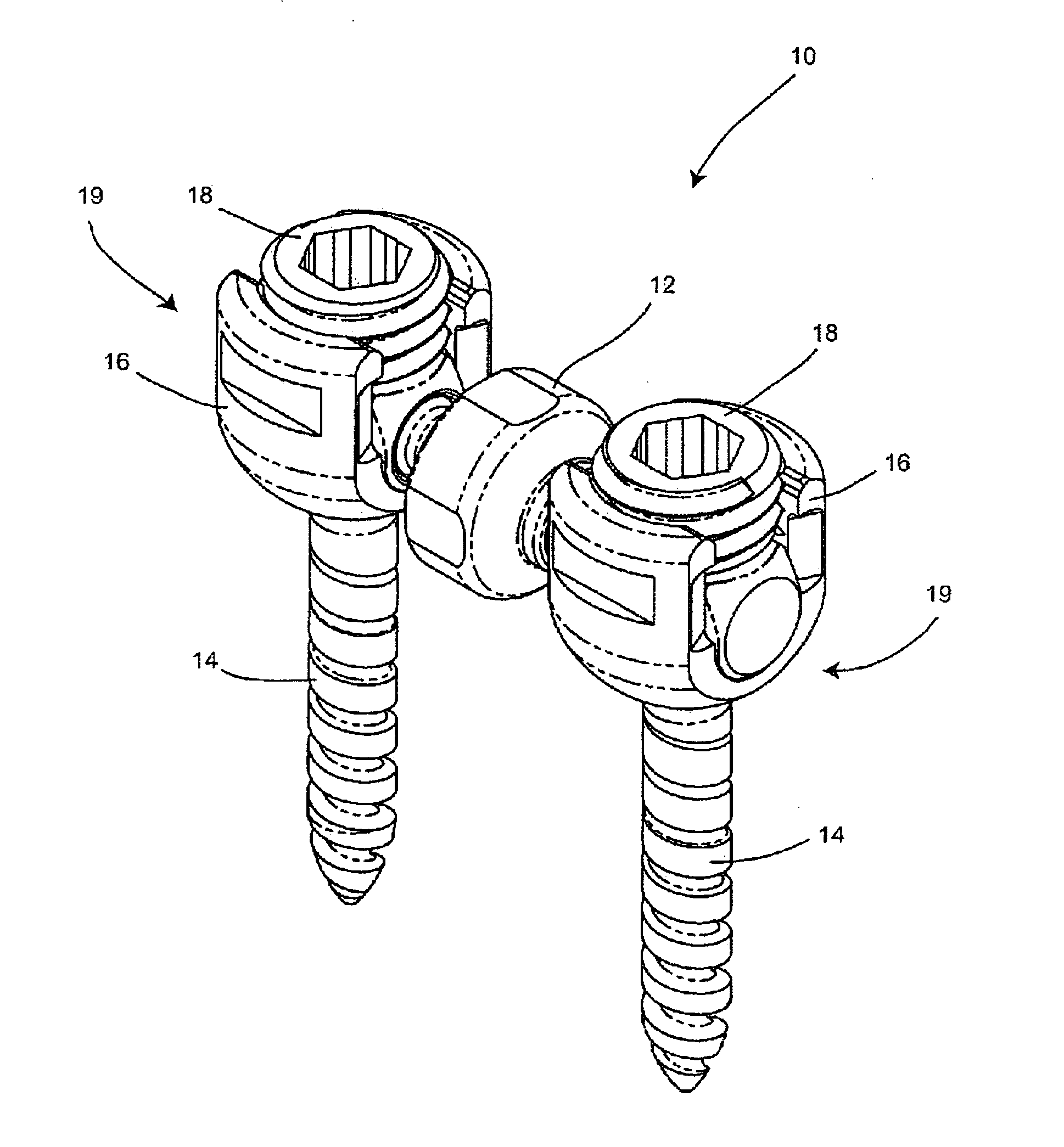
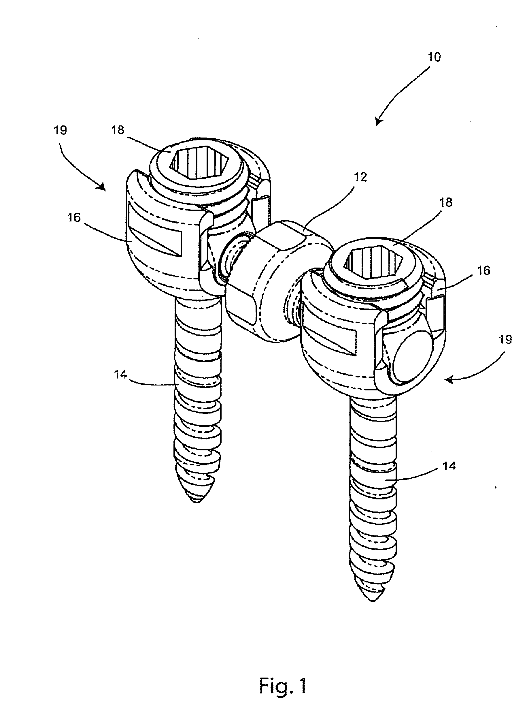
[0045] Referring to FIG. 1, one embodiment of a single level dynamic stabilization system 10 is shown. The dynamic stabilization system 10 preferably includes a stabilizer 12, a pair of fixation members 14, a pair of yokes 16 securable to the fixation members 14, and a pair of set screws 18. The fixation members 14, yokes 16, and set screws 18 may be any of a variety of types known and available in the art, or may optionally be specially designed for operat...


PUM


Abstract

An intervertebral stabilization device and method is disclosed. The device preferably includes a planar spring enclosed within a housing. The housing is joined to an articulation component at either end, and the articulation components have couplings connectable to anchoring components which are securable to adjacent vertebrae. The planar spring can flex and retract providing relative motion between the adjacent vertebrae. The articulation components are ball and socket joints which allow the entire assembly to flexibly follow the curvature of the spine. A fusion rod with articulation components and couplings at either end may be substituted for the spring device. The couplings enable interchangeability between a fusion rod assembly and spring assembly, so that dynamic stabilization can occur at one vertebral level and fusion at the adjacent vertebral level. An overhung spring assembly with a sideways displaced housing which allows for a shorter pedicle to pedicle displacement is also disclosed.

Description

CROSS REFERENCE TO RELATED APPLICATIONS [0001] The present application claims the benefit of U.S. Provisional Patent Application No. 60 / 732,265 filed Oct. 31, 2005, the disclosure of which is hereby incorporated herein by reference.BACKGROUND OF THE INVENTION [0002] The present invention relates to orthopedic medicine, and more particularly to systems and methods for restricting relative motion between vertebrae. [0003] Unfortunately millions of people experience back pain, and such is not only uncomfortable, but can be particularly debilitating. For example, many people who wish to participate in sports, manual labor, or even sedentary employment are unable to do so because of pains that arise from motion of or pressure on the spinal column. These pains are often caused by traumatic, inflammatory, metabolic, synovial, neoplastic and degenerative disorders of the spine. [0004] In a normal spinal column, intervertebral discs that separate adjacent vertebrae from each other serve to p...

Claims


Application Information

Patent Timeline
IPC IPC(8): A61F2/30
CPCA61B17/7004A61B17/7005A61B17/7023A61B17/7028A61B17/7032A61B17/7041
Inventor GERBEC, DANIEL E.FALLIN, T. WADE
Owner STRYKER EURO OPERATIONS HLDG LLC
Why Eureka
Try Eureka