
Tapered anchor for tendon graft

a tendon graft and tapered technology, applied in the field of fixation devices, can solve the problems of significant reduction of the strength of the fixation, significant loss of bone in the fixation site, and sometimes presented complications, and achieve the effect of effective regrowth of bone, strong and rigid fixation of the tendon graft, and minimal disturbance of tissue metabolism and blood circulation

Inactive Publication Date: 2007-05-31
HALKEY ROBERTS CORP
View PDF13 Cites 9 Cited by
  • Summary
  • Abstract
  • Description
  • Claims
  • Application Information

AI Technical Summary

Benefits of technology

[0028] Once the tendon is tensioned by pulling on the sutures existing the top of the femur, the femur bone block may be secured into position within the femoral hole by any conventional method such as by employing an interference screw and / or by using an external tensioning screw as known as the ™“Endo Button” sold by Linvatec. Irrespective of the method employed for tensioning, it is noted that the more the tendon is tensioned to achieve the desired tendon load in the joint, the more the anchor of the invention is wedged tightly into the tapered tunnel in the tibia to more securely grasp the portion of the tendon positioned between the leafs of the anchor. Further, it is noted that the engagement of the anchor within the tapered tunnel prevents the tendon and the femur bone block from moving after being positioned inside the tunnel.
[0030] The anchor of the invention is located totally inside of the tapered hole in the tibia so that no part of it protrudes from the outer surface of the bone. Therefore, it provides an ACL reconstruction fixation apparatus and method that does not damage the tendon graft and minimally disturbs the tissue metabolism and blood circulation while securely grasps the tendon graft inside of the tapered hole, thus enabling maximum filling of the hole with the tendon and facilitating effective re-growth of bone to tendon within tapered hole. Advantageously, the preferred embodiment of the anchor of the invention is bioresorbable and results in a strong and rigid fixation of the tendon graft in ACL reconstruction that does not interfere with non-invasive examinations such as radiographs, MRI or CT.

Problems solved by technology

Unfortunately, during interference screw insertion, technical complications sometimes are presented.
The threads of the screw may damage the graft or the passing sutures, the graft may rotate with the screw so that the optimal position of the graft is lost, the graft may be damaged or the screw may be inserted non parallel (divergent) to the graft thereby significantly decreasing the strength of fixation.
There are also concerns specific to the metal interference screws.
For example, in case of a need for revision surgery, metal screws can significantly complicate the operation, as the hardware inserted in the primary reconstruction may need to be removed, sometimes resulting in considerable loss of bone in the fixation site, and thus, decreasing the strength of the fixation of the revised graft.
Additionally, metal screws have also been shown to disturb postoperative MRI evaluation.
However, other problems may arise, such as the bioabsorbable screw breaking during screw insertion.
This delays the surgical operation and removes mechanically stronger cortical bone, thus reducing the grip of the screw into the bone.
Unfortunately, however, the threaded pin that secures the replacement tendon in the tunnel of the receptor bone is intended to be removed once the bone plug once the bone plug has become grafted.

Method used


Image

  • Tapered anchor for tendon graft
  • Tapered anchor for tendon graft
  • Tapered anchor for tendon graft

Examples


Embodiment Construction

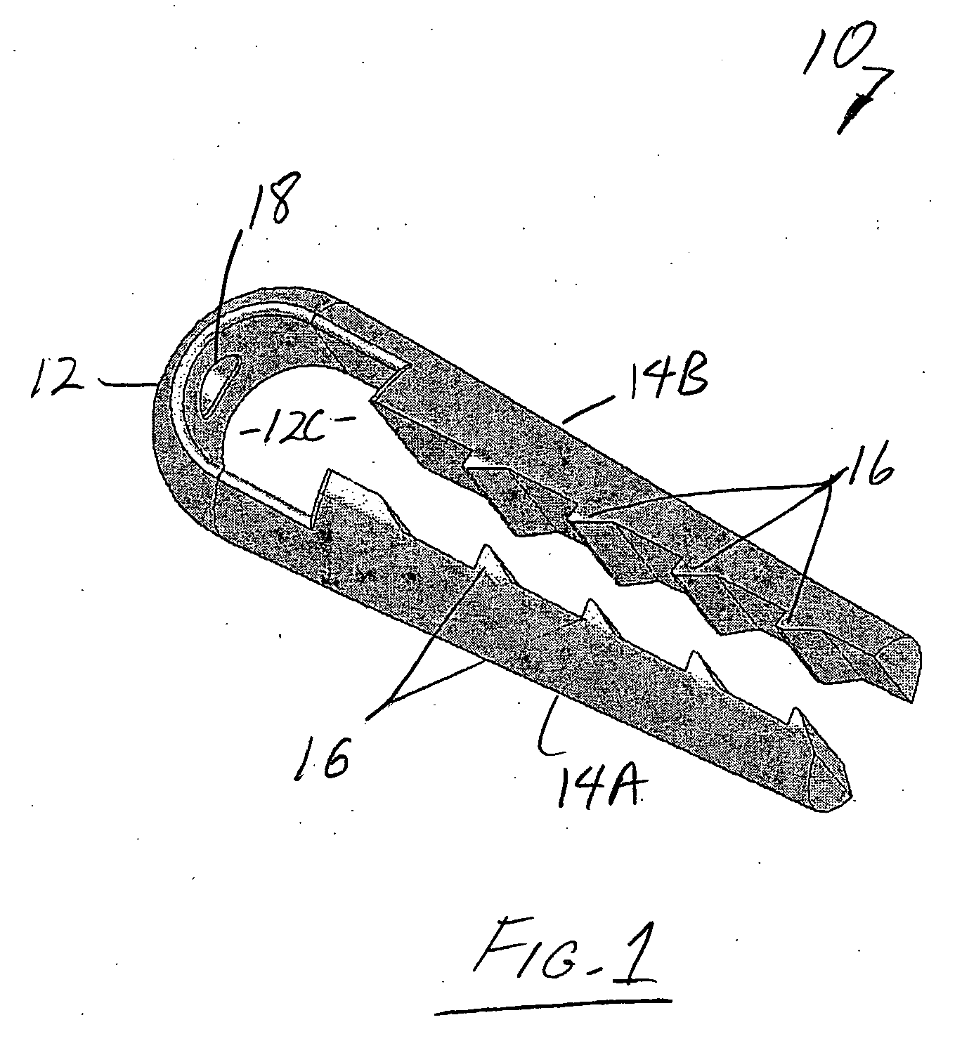
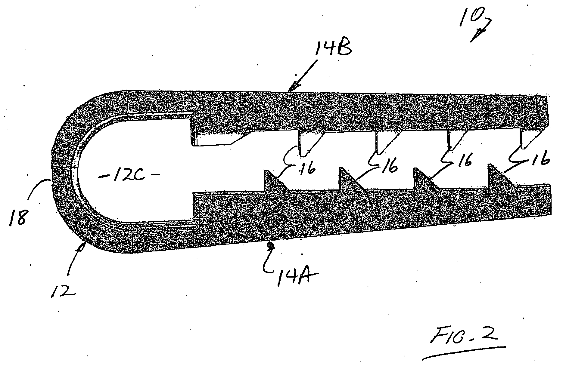
[0040] Referring to FIGS. 1 and 2, the anchor 10 of the invention comprises a loop 12 having two opposing leafs 14A and 14B formed in a “hairpin” configuration. The loop 12 defines a interior cavity 12C and functions as a living hinge to allow the opposing leafs 14A and 14B to flex inwardly toward each other. The outer surfaces of the opposing leafs 14A and 14B are frustro-conically shaped. The inner surfaces of the opposing leafs 14A and 14B comprise inwardly extending teeth 16 along the length thereof in facing alignment with each other. The leaves 14A and 14B define a longitudinal path therebetween from the cavity 12C. An access hole 18 is formed through the loop 12 of the anchor 10 to allow suture access into the cavity 12C (as described hereinafter). Preferably, as best shown in FIG. 2, the inwardly disposed teeth 16 along one leaf 14A are staggered relative to the opposing teeth 16 of the other leaf 14B.

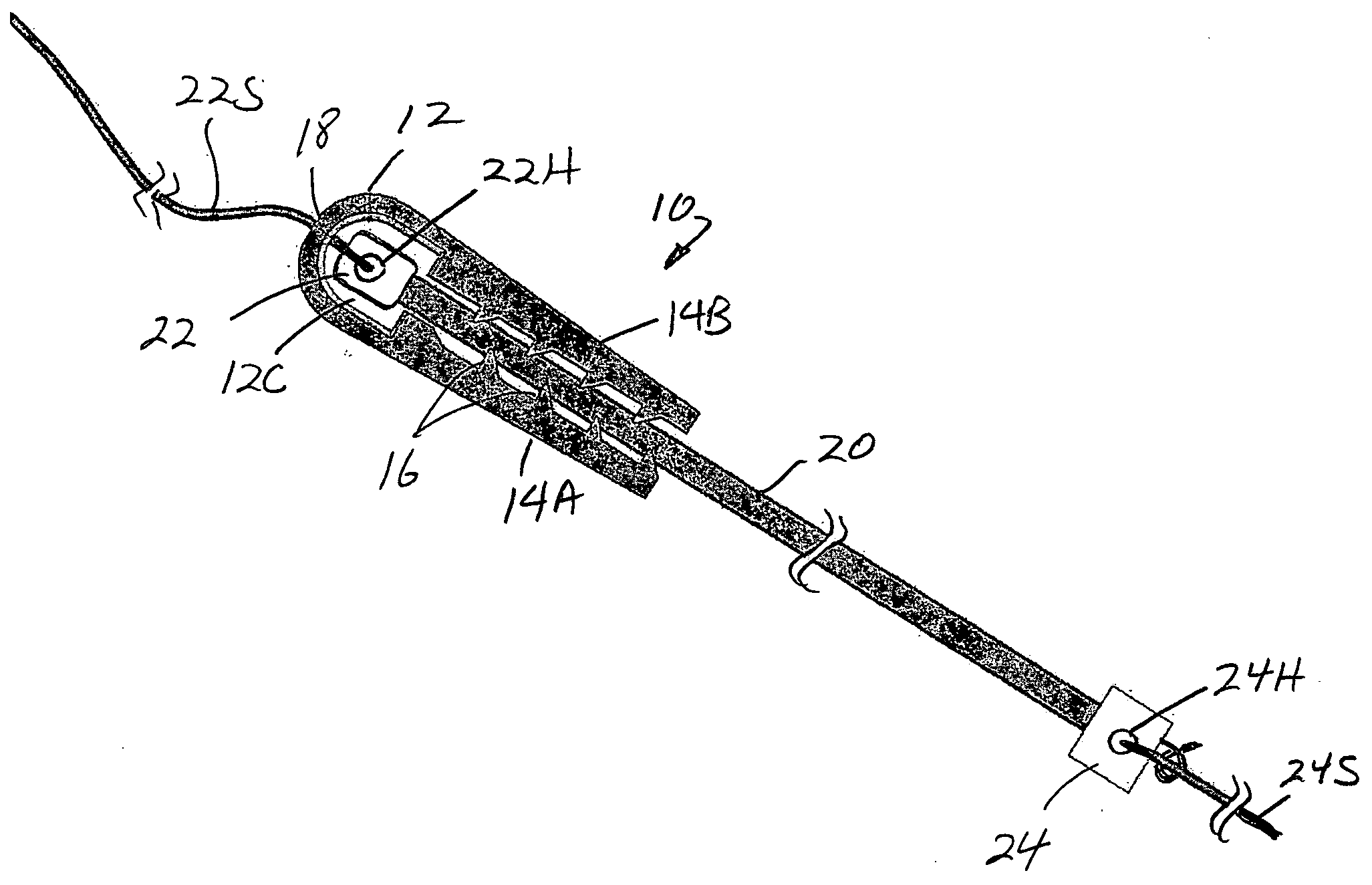
[0041] Referring to FIG. 3, the anchor 10 of the invention is loaded with...


PUM


Abstract

A tapered tendon graft anchor employed during a tendon graft reconstruction surgical procedure. The anchor of the invention comprises a “hair-pin” configuration formed of a loop and two opposing leafs. Each of the leafs include inwardly extending teeth in facing alignment with each other. The outer surfaces of the leafs are tapered to a frustro-conical shape. A harvested tendon with a bone block at one end is positioned with a cavity defined by the loop of the “hair pin” configuration with the tendon positioned between the inwardly extending teeth of the leafs. When the anchor is positioned within a hole in the bone of the joint whose ligament is to be reconstructed, the tendon is tightly grasped by the anchor to securely anchor the tendon in the hole allowing the bone block to be grafted within the hole.

Description

CROSS REFERENCE TO RELATED APPLICATIONS [0001] This application claims the benefit of provisional patent application 60 / 731,333 filed Oct. 28, 2005, the disclosure of which is hereby incorporated by reference herein.BACKGROUND OF THE INVENTION [0002] 1. Field of the Invention [0003] This invention relates to fixation devices that secure a bone tendon bone graft inside bone tunnel. More particularly, this invention relates to surgical devices for attaching a replacement anterior cruciate ligament (ACL) or other tendon / ligament, in a bone. [0004] 2. Description of the Background Art[0005] Presently there exist many surgical techniques employed for replacing, reconstructing or securing synthetic or biological connective tissues to bone surfaces, such as attaching and maintaining an anterior cruciate ligament (ACL) within a knee. More recent surgical procedures for tendon replacement and reconstruction involve auto-grafting a tendon to the site of a torn or dislocated tendon. Early surg...

Claims


Application Information

Patent Timeline
Patent Type & Authority Applications(United States)
IPC IPC(8): A61F2/44
CPCA61B17/0401A61B17/0487A61B2017/0458A61F2/0811A61F2002/0835A61F2002/0864A61F2002/087A61F2002/0882
Inventor COUGHLIN, DOUGLAS M.
Owner HALKEY ROBERTS CORP
Learn More