Locating digital image planar surfaces

a digital image and planar surface technology, applied in the field of digital cameras and image processing for locating planar surfaces, can solve the problems of inability to modify the perspective of most images, constrained case, and often unsatisfactory images, and achieve the effect of reducing camera til

Inactive Publication Date: 2007-06-07
EASTMAN KODAK CO
View PDF14 Cites 11 Cited by
  • Summary
  • Abstract
  • Description
  • Claims
  • Application Information

AI Technical Summary

Benefits of technology

[0010] It is an advantage of the present invention that by using range information planar surfaces in the image can be detected. These detected planar surfaces can be used for modifying the perspective of the digital image to reduce camera tilt, and provide for plane rectification. Furthermore, the planar surfaces can be classified as walls, floors, ceilings, or other planar surfaces.
that by using range information planar surfaces in the image can be detected. These detected planar surfaces can be used for modifying the perspective of the digital image to reduce camera tilt, and provide for plane rectification. Furthermore, the planar surfaces can be classified as walls, floors, ceilings, or other planar surfaces.

Problems solved by technology

Current imaging systems have many deficiencies in that, one an image is captured, the image is often not pleasing because of perspective or because the camera was unintentionally tilted.
However, this method describes a very constrained case, and cannot be used to modify the perspective of most images.
However, this method requires the extraction of lines and vanishing points from an image which are time consuming and can be prone to error.

Method used


Image

  • Locating digital image planar surfaces
  • Locating digital image planar surfaces
  • Locating digital image planar surfaces

Examples


Embodiment Construction

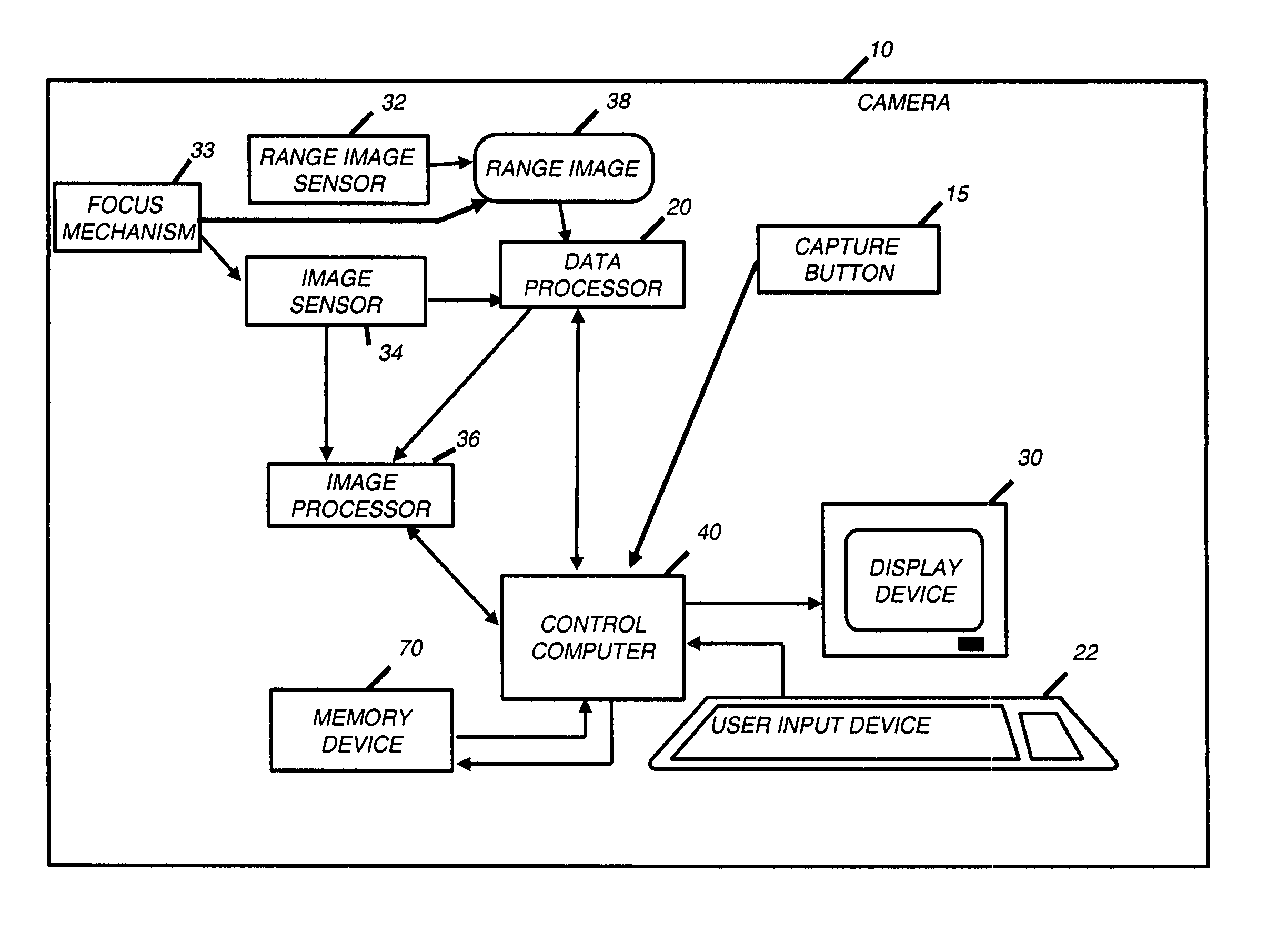
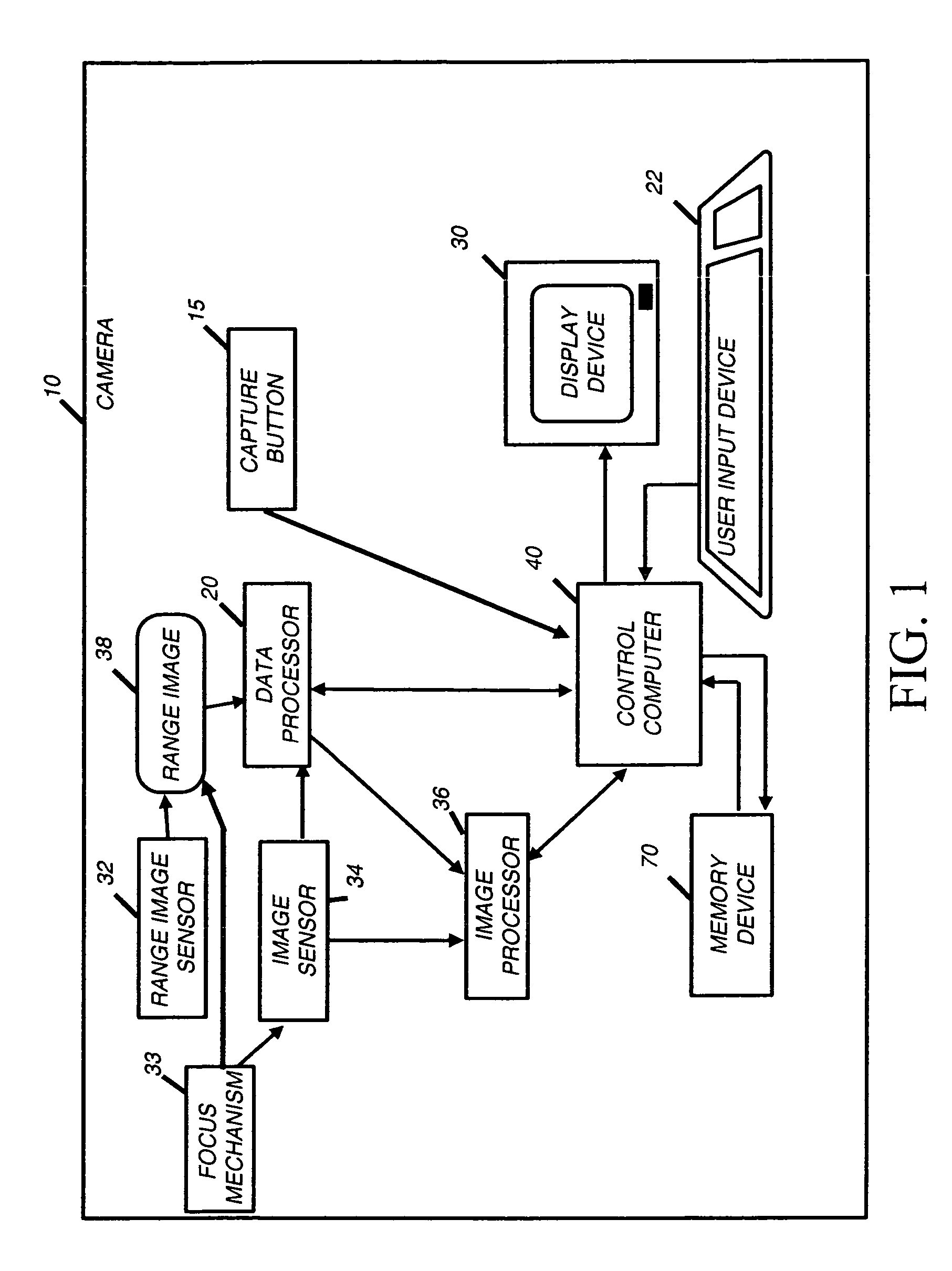
[0024]FIG. 1 shows the inventive digital camera 10. The camera 10 includes user inputs 22. As shown, the user inputs 22 are buttons, but the user inputs 22 could also be a joystick, touch screen, or the like. The user uses the user inputs 22 to command the operation of the camera 10, for example by selecting a mode of operation of the camera. The camera 10 also includes a display device 30 upon which the user can preview images captured by the camera 10 when the capture button 15 is depressed. The display device 30 is also used with the user inputs 22 so that the user can navigate through menus. The display device 30 can be, for example, a LCD or OLED screen, as are commonly used on digital cameras. The menus allow the user to select the preferences for the camera's operation. The camera 10 can capture either still images or images in rapid succession such as a video stream.

[0025] Those skilled in the art will recognize that although in the preferred embodiment a data processor 20,...


PUM


Abstract

A method of processing a digital image of a scene to locate a planar surface in the digital image, includes providing a range information including two or more range values indicating the distance of objects in the scene from a known reference frame; and using a planar model and the range information to locate one or more planar surfaces in the digital image.

Description

CROSS REFERENCE TO RELATED APPLICATIONS [0001] Reference is made to commonly assigned U.S. Patent Application Serial No. ______ filed concurrently herewith entitled “Detecting Objects of Interest in Digital Images” by Andrew C. Gallagher et al and U.S. Patent Application Serial No. ______ filed concurrently herewith entitled “Adjusting Digital Image Exposure and Tone Scale” by Andrew C. Gallagher et al, the disclosures of which are incorporated herein. FIELD OF INVENTION [0002] The field of the invention relates to digital cameras and image processing for locating planar surfaces in digital images and modifying the perspective of an image based on range information. BACKGROUND OF THE INVENTION [0003] Current imaging systems have many deficiencies in that, one an image is captured, the image is often not pleasing because of perspective or because the camera was unintentionally tilted. [0004] Image warping is a well-known tool that may be used to modify the apparent perspective of an ...

Claims


Application Information

Patent Timeline
Patent Type & Authority Applications(United States)
IPC IPC(8): H04N5/225
CPCG06K9/00201G06K9/00691G06T3/00G06T7/004H04N5/2226H04N5/232H04N5/23212H04N5/23219H04N5/235H04N5/2351H04N5/2355H04N5/243H04N5/2628H04N13/0022G06T7/70H04N13/128G06V20/64G06V20/36H04N23/611H04N23/80H04N23/70H04N23/741H04N23/76H04N23/71
Inventor GALLAGHER, ANDREW C.CAHILL, NATHAN D.FIELDING, GABRIELRAY, LAWRENCE A.
Owner EASTMAN KODAK CO
Why Eureka
Try Eureka