Method, system and apparatus for optical phase modulation based on frequency shift

Inactive Publication Date: 2007-06-07
QI BING +3
View PDF14 Cites 43 Cited by
  • Summary
  • Abstract
  • Description
  • Claims
  • Application Information

AI Technical Summary

Benefits of technology

[0033] Furthermore, the present invention is not limited to single distance/location measurements. By employing Fourier analysis, electromagnetic signals (including light signals) can be detected from multiple locations and reflecting/disturbance sites can be located. Therefore, the method in the present invention can be used for applications such as fault location and detection, connector location and detection, and sensor location and detection, along an optical fibre or in free space. This is different from the OTDR (optical time-domain reflectometry) method, which is based on time measurements for locating reflections. The present invention is also different from the previously mentioned OFDR as well as the OLCR (optical low-coherence reflectometry), since both OFDR and OLCR require a reference arm. As an additional advantage, the method described in the present invention does not require dispersion compensation, which is necessary in the OLCR method.
[0034] In another application of the present invention, the refractive index of a medium can be deduced given the frequency change and the physical distance the signal travels. Specifically, by measuring the refractive index using the present invention for different frequencies of light (for example, by employing a tunable laser), one can obtain the dispersion of the medium. This method of measuring dispersion is different from the other established methods, such as the OFDR, the time-of-flight technique, and the phase-shifted method. The difference between the present invention and the OFDR has already been discussed previously. The time-of-flight technique is based on a very different principle, in which very short pulses are used and the arrival time of the pulses are measured. The phase-shifted method is also based on a very different principle: the tunable laser source is intensity modulated (usually by an RF signal) and the phase of the intensity modulation at the receiver is compared to a reference electrical signal to determine the optical delay the signal experiences, from which the refractive i

Problems solved by technology

OCDRs, on the other hand, can offer much higher resolution (tens of micro-meters) based on low-coherence interference, but have very limited dynamic range (tens of centimeters) due to the limited scanning range of the reference arm.
All these techniques are quite complicated to implement, and they either suffer from a small dynamic range or a low resolution.
Though these are well-established te

Method used


Image

  • Method, system and apparatus for optical phase modulation based on frequency shift
  • Method, system and apparatus for optical phase modulation based on frequency shift
  • Method, system and apparatus for optical phase modulation based on frequency shift

Examples


example 1

[0037] In a representative embodiment of the system and method provided by the present invention, a phase modulator based on frequency shift is described.

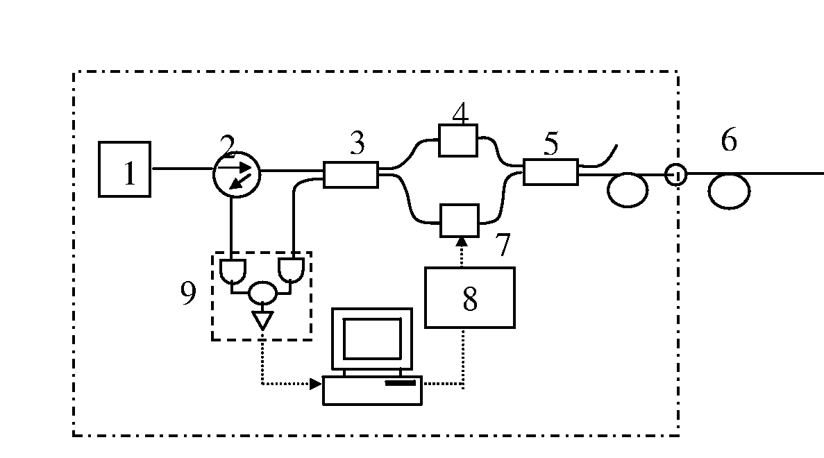
[0038] One realization is shown in FIG. 1. The phase modulator consists of two AOMs and a fiber spool between them. The first AOM up-shifts the frequency of the input light signal byf, which is the central frequency of acoustic driver, while the second AOM will down-shift the frequency by the same amount. So after the light pulse goes through the whole device, there is no net frequency shift. The phase modulation is achieved by varying the acoustic frequency.

[0039] Suppose the optical length between AOM1 and AOM2 is nL, then the relative phase change induced by the change of acoustic frequency is Δϕ=2⁢π⁢ ⁢nL⁢ ⁢Δ⁢ ⁢fC

[0040] For example, if L=10 m, n=1.46, to achieve a 2π phase change, the change of acoustic frequency is about 10 MHz, which can be easily realized by commercial AOM operating at frequency modulation mode. Potentiall...

example 2

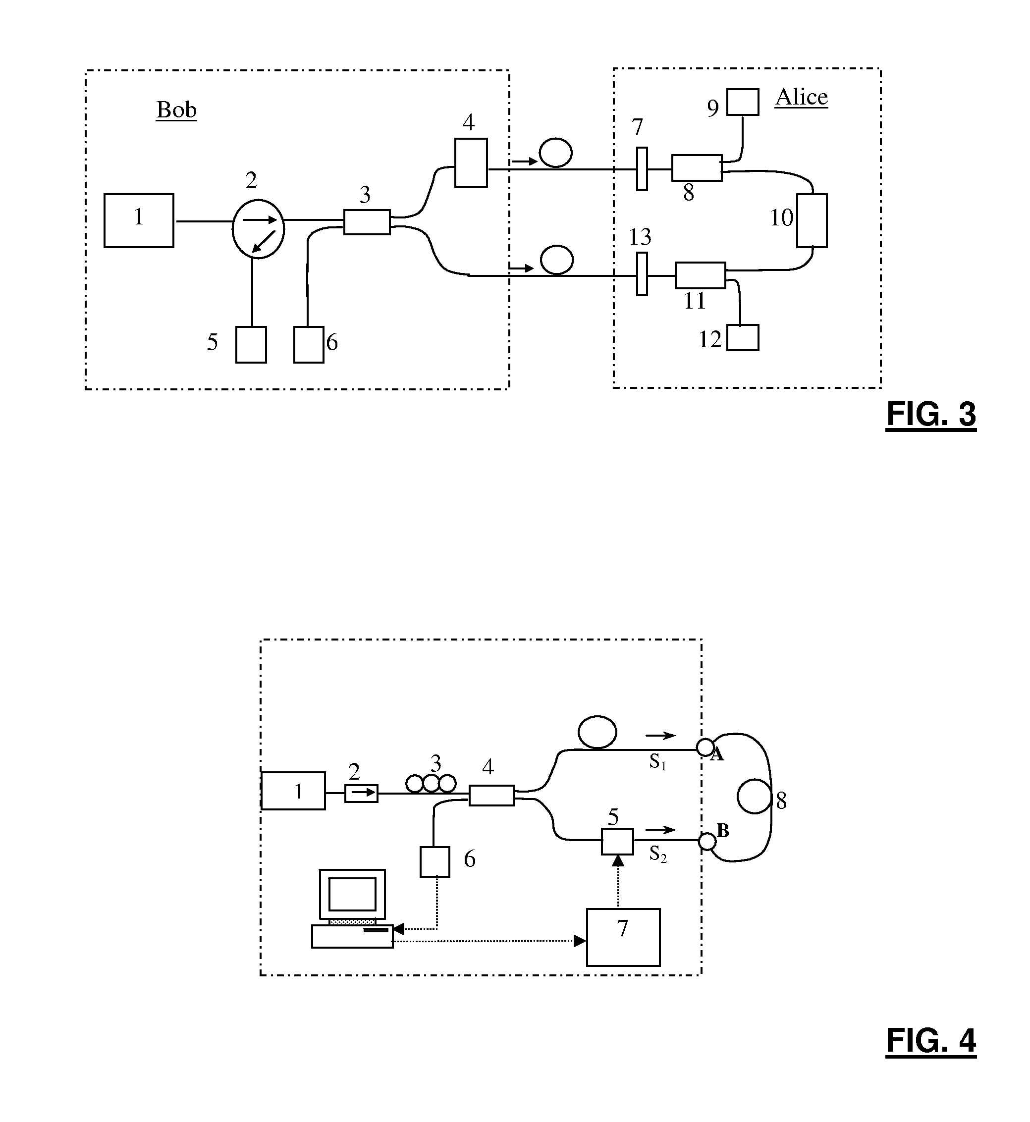
[0050] In a representative embodiment of the system and method provided by the present invention, a Sagnac QKD system employing phase modulator based one frequency shift is described.

[0051] A proposed QKD system based on the AOM-based phase modulator is shown in FIG. 3. On Alice's side, two classical photo detectors (PD1, PD2) and two wavelength filters (F1, F2) are introduced to fight against Trojan horse attack. These photo detectors can also be used for synchronization purpose. To realize BB84 protocol, Alice randomly encodes her information on the relative phase between clockwise and counterclockwise light pulses with PM1, while Bob randomly choose his measurement basis with PM2.

[0052] We remark that the newly developed decoy-state QKD protocol, which improves the secure key generation rate of practical QKD system dramatically, can be easily realized in this setup. In decoy-state QKD, Alice randomly adds in decoy pulses, which are used for testing the communication channel, in...

example 3

[0053] In a representative embodiment of the present invention, a high-resolution, large dynamic range fibre length measurement system is described, based on a frequency shifted asymmetric Sagnac interferometer incorporating an acousto-optic modulator (AOM). By sweeping the driving frequency of the AOM, which is asymmetrically placed in the Sagnac loop, the optical length of the fibre can be determined by measuring the corresponding variation in the phase delay between the two counter-propagating light beams. Stated another way, the acoustic wave generates a propagating diffraction grating inside the crystal. Consequently, the 1st-order diffracted light is Doppler shifted by an amount equal to the frequency of the acoustic signal f. Combined with a high-resolution data processing algorithm, this rather simple and robust system setup yields a dynamic range from a few centimeters to 60 km, limited only by the availability of long fibres, with a precision on the order of 10−6 for long ...


PUM


Abstract

The present invention provides an optical phase modulation method using optical frequency shift devices. By accurately controlling the frequency shift, the phase delay experienced by the light signal through an optical medium (fibre, free space, vacuum, or other) can be controlled with high resolution. Hence, phase change can be achieved through frequency change. This technique can be applied to a wide range of applications whenever phase modulation is needed, such as in various phase-shifted keying techniques in optical communications, and in optical metrology. The disclosed phase modulation method can also be used as a phase encoding technique in quantum key distribution.

Description

FIELD OF INVENTION [0001] This invention relates generally to phase modulation methods and systems. This invention relates more particularly to a method and system for implementing optical phase modulation. The invention also relates to methods and system for measuring optical path length, which can be used to determine fibre length and dispersion. The invention also relates to methods and system for locating optical reflection sites along a light path, such as in fibre sensor array multiplexing. BACKGROUND OF INVENTION [0002] Optical phase modulation is commonly employed in optical communications and quantum communications, where information can be encoded into the phase of the lightwave carrier. Conventional phase modulation methods employ a change either in the refractive index (such as an electro-optic modulator), or in the distance (such as a piezo-electric transducer-based phase modulator). [0003] Precise fibre length measurement is important in both optical communication and ...

Claims


Application Information

Patent Timeline
IPC IPC(8): H04B10/04H04B10/12
CPCH04B10/30H04B10/548H04B10/5561
Inventor QI, BINGQIAN, LILO, HOI-KWONGZHAO, YI
Owner QI BING
Why Eureka
Try Eureka