
Touch panel

a technology of touch panel and electrode, applied in the direction of coupling device connection, instrument, static indicating device, etc., can solve the problems of preventing the electrical connection of wiring patterns to electrodes stably, silver migration producing minute precipitates between, and affecting the stability of the insulation

Active Publication Date: 2007-06-07
PANASONIC CORP
View PDF4 Cites 19 Cited by
  • Summary
  • Abstract
  • Description
  • Claims
  • Application Information

AI Technical Summary

Benefits of technology

[0013] This touch panel allows the wiring patterns to be connected electrically to the electrodes stably, and insulates between the wiring patterns and between electrodes, thus being reliable.

Problems solved by technology

These wiring patterns and electrodes contain silver, and hence, may be sulfurized or cause silver migration producing minute precipitates between the patterns when the wiring patterns and electrodes are used in an environment including a large amount of moisture or gas.
In this case, the wiring patterns cannot be connected electrically to the electrodes stably, and prevented from having a stable insulation between the wiring patterns or between the electrodes.

Method used


Image

  • Touch panel
  • Touch panel
  • Touch panel

Examples


Embodiment Construction

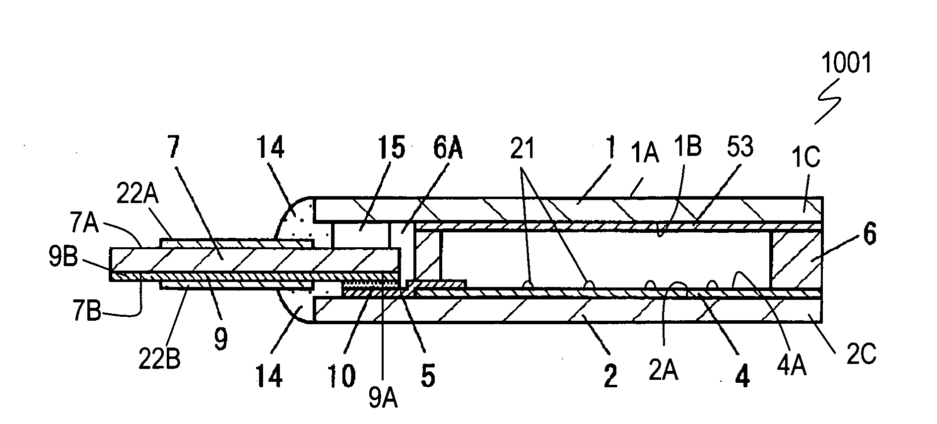
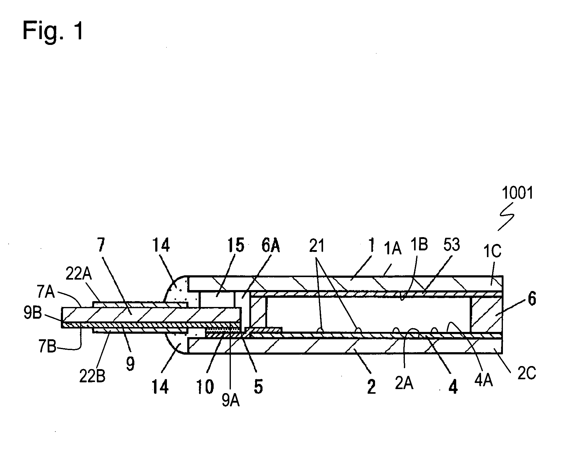
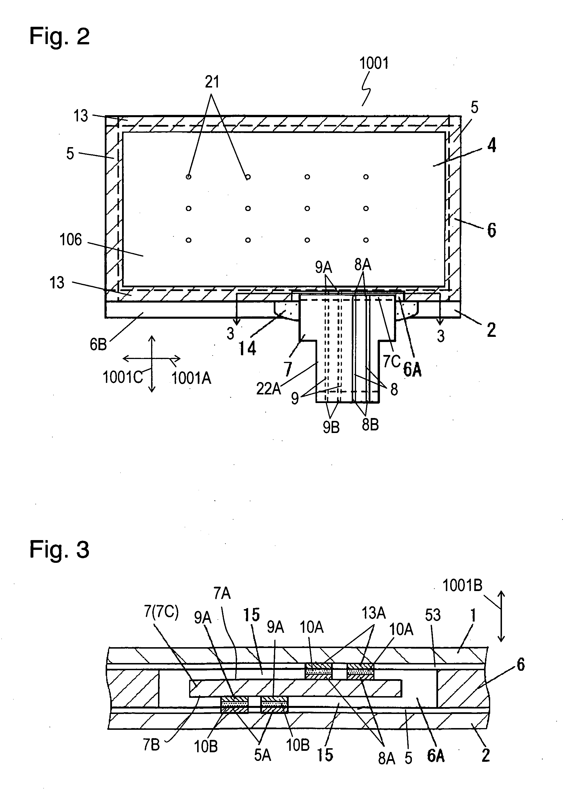
[0019]FIGS. 1 and 2 are a side sectional view and a plane sectional view of touch panel 1001 according to an exemplary embodiment of the present invention, respectively. FIG. 3 is a partial cross sectional view of touch panel 1001 at line 3-3 shown in FIG. 2. Upper board 1 is light-transmissible and is made of insulating flexible film, such as polyethylene terephthalate film or polycarbonate film. Lower board 2 is light-transmissible and is made of insulating material, such as glass, acryl, or polycarbonate. Upper resistor layer 53 made of light-transmissible resistor material, such as indium tin oxide or tin oxide, is formed on lower surface 1B of upper board 1 by, for example, a sputtering method. Lower resistor layer 4 made of resistor material, such as indium tin oxide or tin oxide is formed on upper surface 2A of lower board 2 by, for example, a sputtering method. Dot spacers 21 made of insulating resin, such as epoxy or silicone are formed on upper surface 4A of lower resistor...


PUM


Abstract

A touch panel includes a light-transmissible upper board, an upper resistor layer on a lower surface of the upper board, a light-transmissible lower board, a lower resistor layer provided on an upper surface of the lower board and facing the upper resistor layer with a predetermined distance, a spacer having a substantial frame shape between an outer periphery of the lower surface of the upper board and an outer periphery of the upper surface of the lower board, upper electrodes extending from both ends of the upper resistor layer, lower electrodes extending from both ends of the lower resistor layer, a wiring board, and wiring patterns on the wiring board. The spacer has a cutout portion provided therein. The upper and lower electrodes have portions located at the cutout portion of the spacer. The wiring board has an end located at the cutout portion. The wiring patterns are connected to the portions of the upper electrodes and the portions of the lower electrodes, respectively. An elastic adhesive seals the cutout portion of the spacer. This touch panel allows the wiring patterns to be connected electrically to the electrodes stably, and insulates between the wiring patterns and between electrodes, thus being reliable.

Description

TECHNICAL FIELD [0001] The present invention relates to a touch panel used for operations of various electronic devices. BACKGROUND ART [0002] An electronic device, such as a mobile phone and a car navigation system, has had higher performance and various functions, and often includes a light-transmissible touch panel attached onto a front surface of a display element, such as a liquid crystal display. An operator presses the touch panel with a finger or a pen while looking at the display element through the touch panel, thereby switching the functions to operate the device. This touch panel is demanded to be reliably operated and not to prevent the operator from looking at the display element. [0003]FIGS. 4 and 5 are a side sectional view and a plane sectional view of conventional touch panel 5001 disclosed in Japanese Patent Laid-Open Publication No. 2005-11312, respectively. Upper board 501 has a film shape and is light-transmissible. Light-transmissible upper resistor layer 503 ...

Claims


Application Information

Patent Timeline
IPC IPC(8): H01R24/00
CPCG06F3/0412G06F3/045
Inventor NAKANISHI, AKIRAFUJII, SHIGEYUKI
Owner PANASONIC CORP
Learn More