Supercharge Your Innovation With Domain-Expert AI Agents!

Piston for fluid container

a fluid container and piston technology, applied in the field of pistons, can solve the problems of deformation of the seal between the piston and the inner wall, the inability of the conventional piston to maintain fulid tightness, and the deformation of the seal with time, and achieve the effect of simple structure and high fluid tightness

Inactive Publication Date: 2007-06-14
MASUDA MASATOSHI
View PDF0 Cites 10 Cited by
  • Summary
  • Abstract
  • Description
  • Claims
  • Application Information

AI Technical Summary

Benefits of technology

"The present invention provides a piston and a fluid container that can securely maintain fluidtightness for a long period of time. The piston is designed to be engaged inside a cylindrical container and includes a sliding member and a support member with concentric flexions to ensure a tight seal against the inner wall of the container. The piston can be used in a tapered cylindrical container and includes at least one additional concentric flexion. The technical effects of the invention include improved fluidtightness, durability, and reliability of the piston and fluid container."

Problems solved by technology

However, a cylinder produced by injection molding, for example, often has a tapered inner wall for production process convenience, and in that case, the conventional piston could not maintain fulidtightness because an internal diameter of the cylinder changes whereas the diameter of the piston does not significantly change.
Further, the conventional piston is normally designed for short term use, and the seal between the piston and the inner wall tends to be degraded with time.

Method used


Image

  • Piston for fluid container
  • Piston for fluid container
  • Piston for fluid container

Examples


embodiment 1

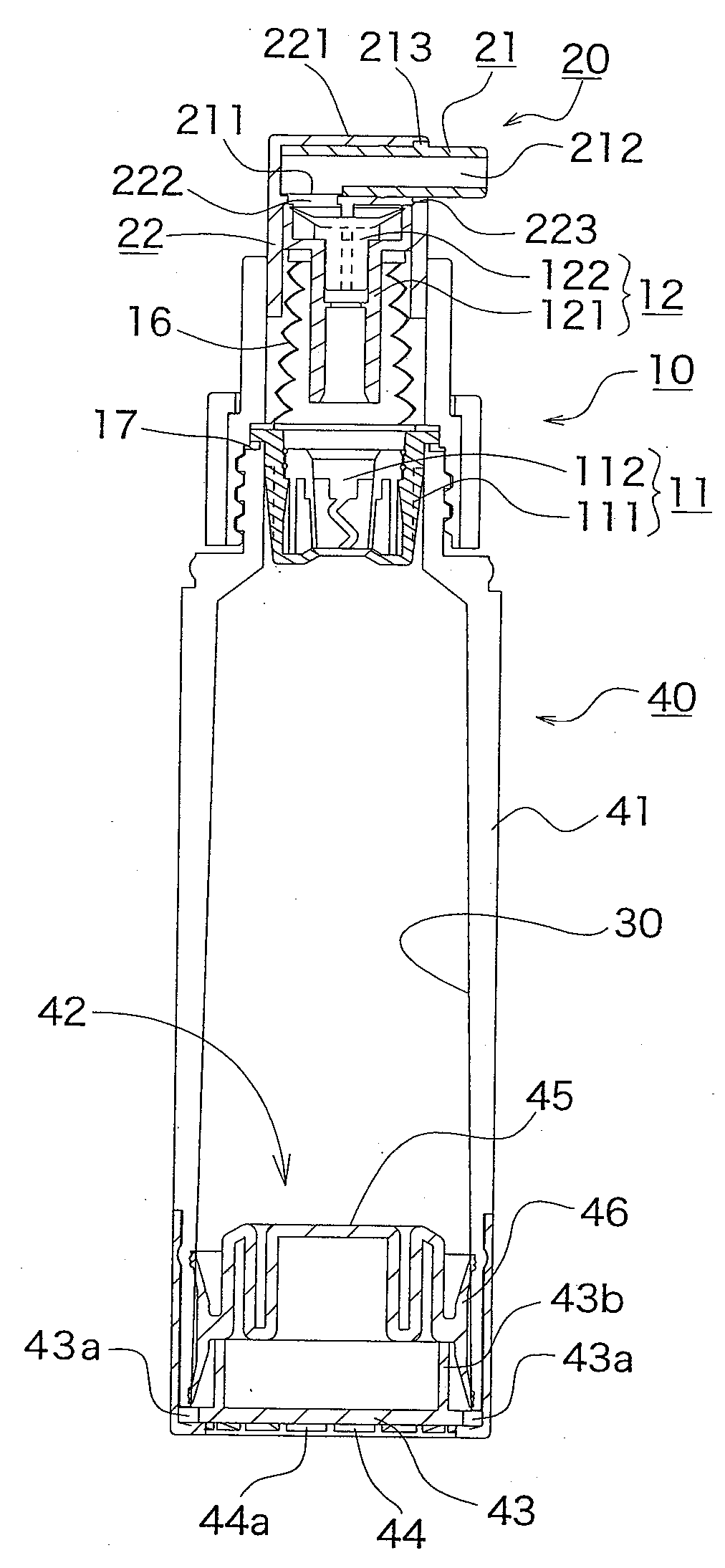
[0085] FIGS. 16(a)-(c) are explanatory views each showing the piston member 42′ in an alternative embodiment. While three flexions 423a, 423b, 423c are formed in the piston member 42 in the fluid container , five flexions 423a, 423b, 423′c, 423d, 423e also can be formed in this embodiment as shown in FIGS. 16(a)-(c). Additionally, the number of flexions formed can be other than five, or it can be a single one.

embodiment 2

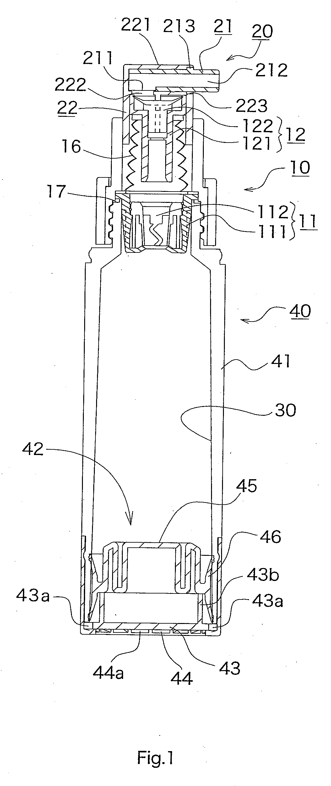
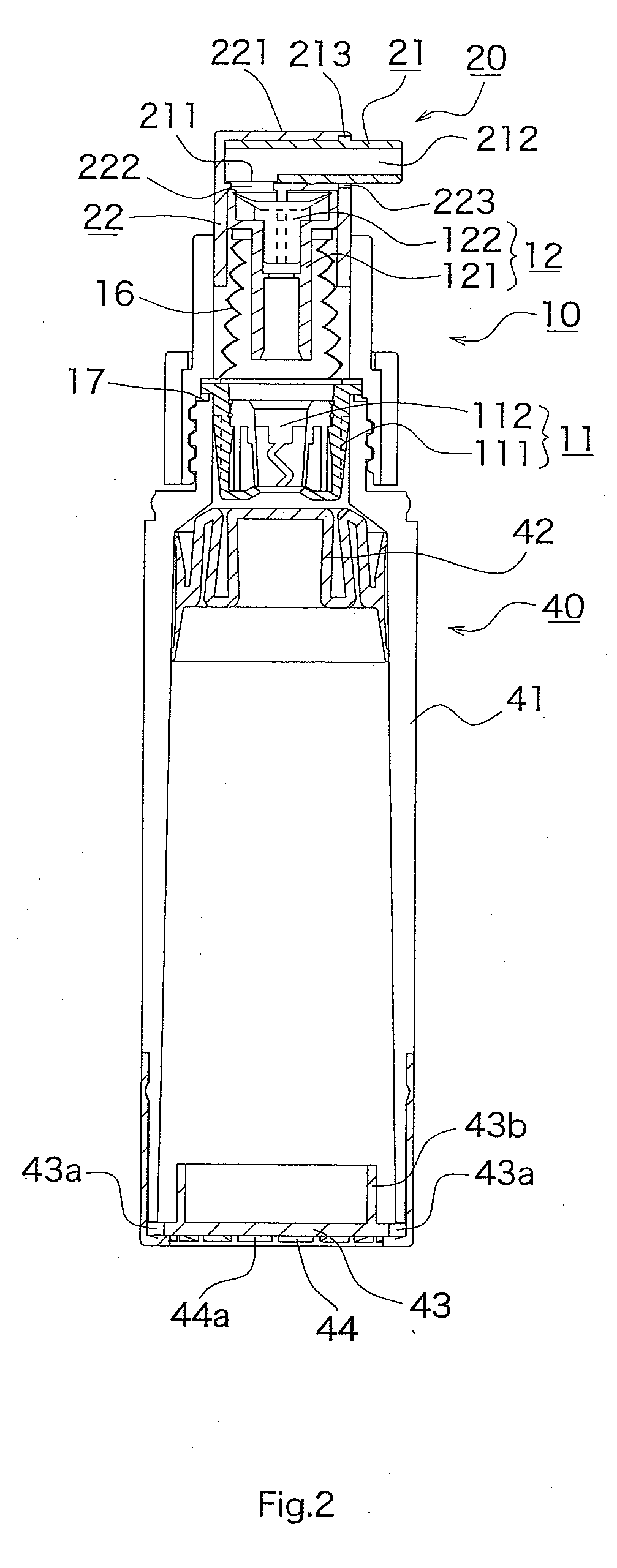
[0086]FIGS. 17 and 18 are longitudinal cross sections showing the fluid container according to a further alternative embodiment (Embodiment 2). While a cylinder member 41 in the fluid container according to the embodiments previously described has a tapered inner surface 30, even when the cylinder member having a non-tapered inner surface 30′ as shown as a cylinder member 41′ of a container 40′ in FIGS. 17 and 18 is used, the piston member 42 shown in FIGS. 15(a)-(c) and 16(a)-(c) also can be used.

[0087] According to an embodiment of the present invention, when the piston comprises an elastic member in which a concentric flexion with an outer perimeter is formed in a plane perpendicular to a traveling direction of the piston inside the cylinder and has momentum from the central portion in an outer peripheral direction, it becomes possible to secure airtightness even when a cylinder diameter changes.

[0088] According to another embodiment of the present invention, when in the fluid c...


PUM


Abstract

A piston configured to be engaged inside a cylindrical container includes: a sliding member having an upper fluidtight portion and a lower fluidtight portion; and a support member connected to the sliding member and having concentric flexions for urging the sliding member against the inner wall of the cylindrical container. The upper and lower fluidtight portions are each constituted by at least one annular convex bump portion having a thickness which is the greatest at a point where the annular convex bump portion is in contact with the inner wall of the cylinder.

Description

[0001] This is a continuation of U.S. patent application Ser. No. 10 / 872,021, field Jun. 18, 2004, which claims foreign priority under 35 U.S.C. §119 to Japanese Patent Application No. 2003-191197, filed Jul. 3, 2003, the disclosure of which is herein incorporated by reference in their entirety.BACKGROUND OF THE INVENTION [0002] This invention relates generally to a piston engaged inside a cylindrical container, which serves as a movable bottom of the container and functions for enhancing fluidtightness inside the container. [0003] As a piston for enhancing airtightness inside a cylinder, Japanese Patent Laid-open No. 1996-280804 discloses a piston for a syringe, for example. However, a cylinder produced by injection molding, for example, often has a tapered inner wall for production process convenience, and in that case, the conventional piston could not maintain fulidtightness because an internal diameter of the cylinder changes whereas the diameter of the piston does not signific...

Claims


Application Information

Patent Timeline
Patent Type & Authority Applications(United States)
IPC IPC(8): G01F11/00B65D37/00B65D88/54B65D83/76B05B11/00B65D83/00B67D7/60
CPCB05B11/0029B05B11/0048B05B11/0062B05B11/3035B05B11/3067B05B11/3077B65D83/0033G01F11/028B05B11/028B05B11/1035B05B11/1067B05B11/1069B05B11/1077
Inventor MASUDA, MASATOSHI
Owner MASUDA MASATOSHI
Features
  • R&D
  • Intellectual Property
  • Life Sciences
  • Materials
  • Tech Scout
  • Unparalleled Data Quality
  • Higher Quality Content
  • 60% Fewer Hallucinations
Learn More