Rotorcraft control system and method of using

a control system and rotorcraft technology, applied in the direction of rotocraft, vehicles, wing lift eficiency, etc., can solve the problems of insufficient system redundancy, low energy efficiency, and lack of higher harmonic control capability

Inactive Publication Date: 2007-06-14
SIKORSKY AIRCRAFT CORP
View PDF29 Cites 25 Cited by
  • Summary
  • Abstract
  • Description
  • Claims
  • Application Information

AI Technical Summary

Benefits of technology

[0009] It is an object of the present invention ...

Problems solved by technology

Although simple to implement, the swashplate control system suffers from several shortcomings, including large drag forces which significantly reduce energy efficiency, ...

Method used


Image

  • Rotorcraft control system and method of using
  • Rotorcraft control system and method of using
  • Rotorcraft control system and method of using

Examples


Embodiment Construction

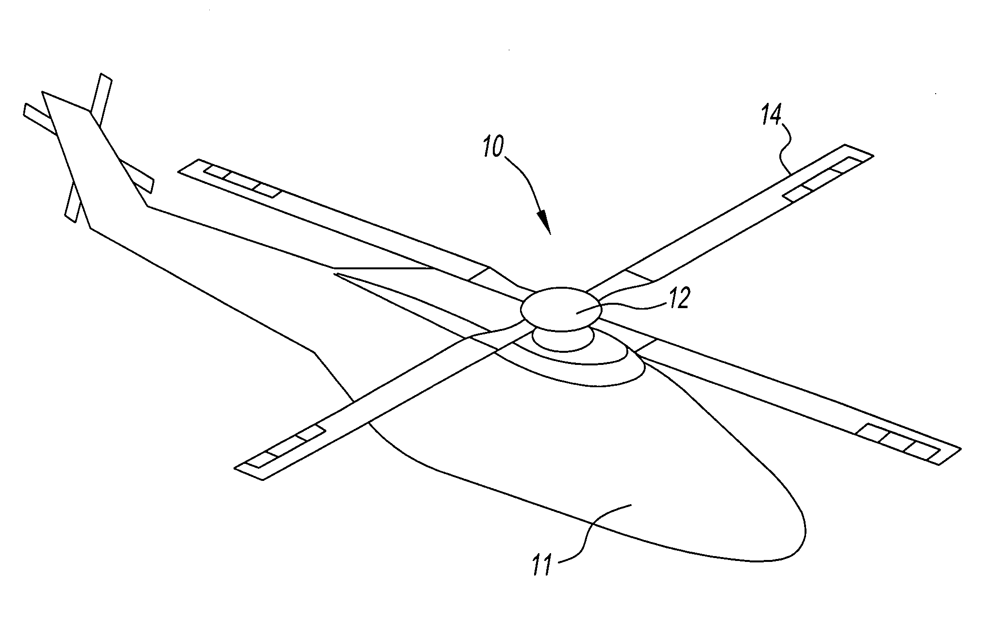
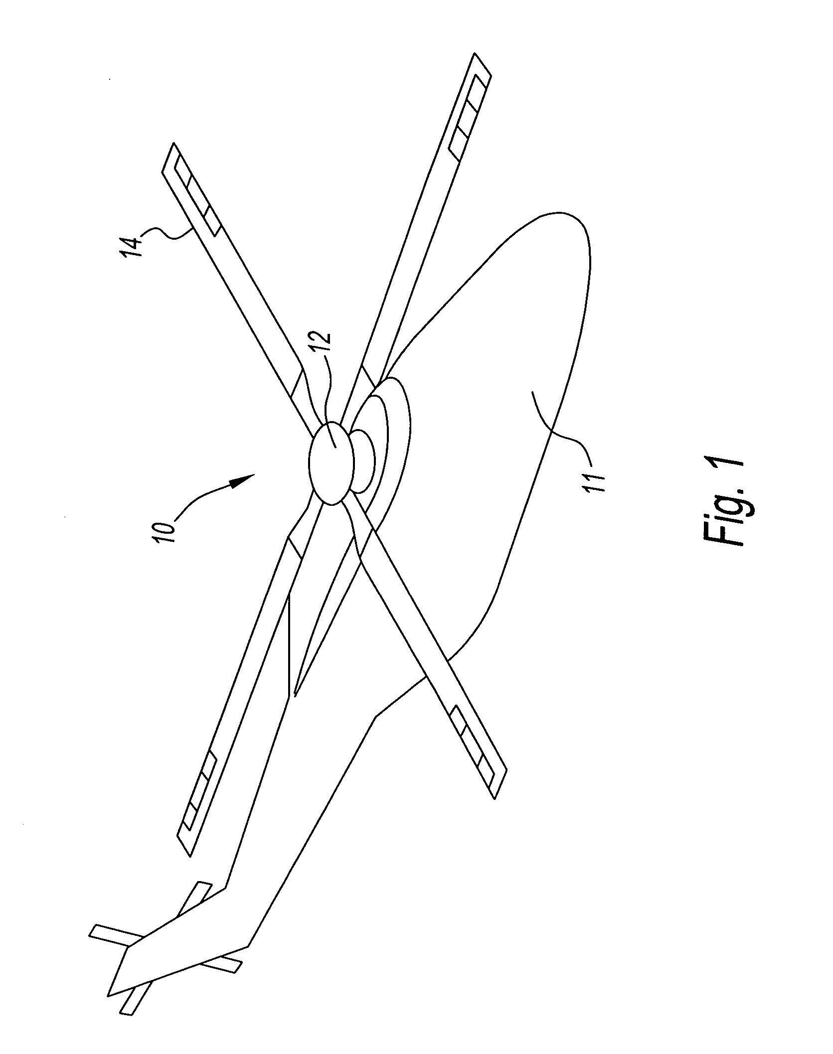
[0021]FIG. 1 schematically illustrates an exemplary embodiment of a rotorcraft control system 10 connected to a rotorcraft body 11 (i.e., an airframe) according to the present disclosure. The control system 10 includes a rotor assembly 12 and at least two or more rotor blades 14 (four shown). Advantageously, the control system 10 is configured such that the rotor assembly 12 does not include a swashplate to control the pitch of the rotor blades as generally known in the prior art.

[0022] For purposes of clarity, the control system 10 is illustrated in use with an exemplary helicopter (shown in phantom). Although a helicopter with a single main rotor is illustrated in FIG. 1, other rotorcraft will also benefit from the present invention such as a rotorcraft with counter-rotating rotors or tandem rotors. Additionally, it is to be understood that the control system of the present invention may be incorporated into other aircraft as well, such as, for example, compound rotary-wing aircr...


PUM


Abstract

A rotorcraft control system for effectuating primary flight control and high harmonic control. The control system preferably including at least one primary flap, at least one primary actuator used principally for primary flight control, at least one secondary flap, and at least one secondary actuator used principally for high harmonic control. The at least one secondary flap and the at least one secondary actuator preferably may also be used to enhance primary flight control under some flight conditions.

Description

CROSS REFERENCE TO RELATED APPLICATION [0001] This application is related to U.S. Application No. 0002563USU, entitled “BRUSHLESS DIRECT CURRENT MOTOR BASED LINEAR OR ROTARY ACTUATOR FOR HELICOPTER ROTOR CONTROL” filed simultaneously herewith, the contents of which are incorporated by reference herein. BACKGROUND OF THE INVENTION [0002] 1. Field of the Invention [0003] The present disclosure relates to rotorcraft control systems. More specifically, the present disclosure relates to rotorcraft control systems in which trailing-edge flaps are used for both primary flight control (PFC) and higher harmonic control (HHC). [0004] 2. Description of Related Art [0005] For over a half-century, rotorcraft, such as, but not limited to, helicopters have included control systems using a swashplate for effectuating primary flight control of the rotorcraft. Although simple to implement, the swashplate control system suffers from several shortcomings, including large drag forces which significantly...

Claims


Application Information

Patent Timeline
IPC IPC(8): B64C27/52
CPCB64C27/001Y02T50/34B64C2027/7266B64C27/615Y02T50/30
Inventor CHAUDHRY, ZAFFIRCAO, MINGWAKE, BRIAN E.
Owner SIKORSKY AIRCRAFT CORP
Why Eureka
Try Eureka