
Manuscript conveyor guide used for a manuscript reader unit

a conveyer guide and manuscript technology, applied in the direction of electrographic process, transportation and packaging, instruments, etc., can solve the problem of uneven reading of manuscripts, achieve the effect of suppressing uneven reading, suppressing uneven reading, and effective suppressing uneven reading

Active Publication Date: 2007-06-14
TSUCHIYA HIROAKI
View PDF2 Cites 0 Cited by
  • Summary
  • Abstract
  • Description
  • Claims
  • Application Information

AI Technical Summary

Benefits of technology

[0009] It is therefore an object of the present invention to provide a manuscript conveyer guide which is disposed neighboring the contact glass plate on the manuscript discharge side and effectively suppresses the unevenness in the reading of the manuscript.
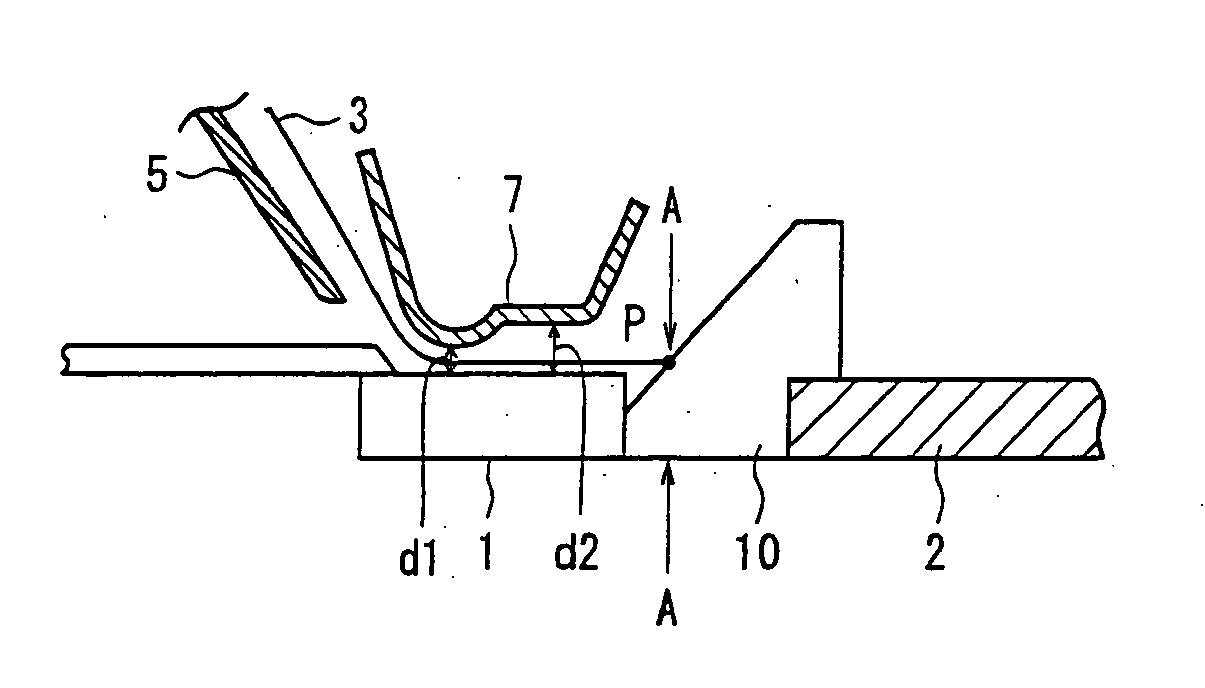
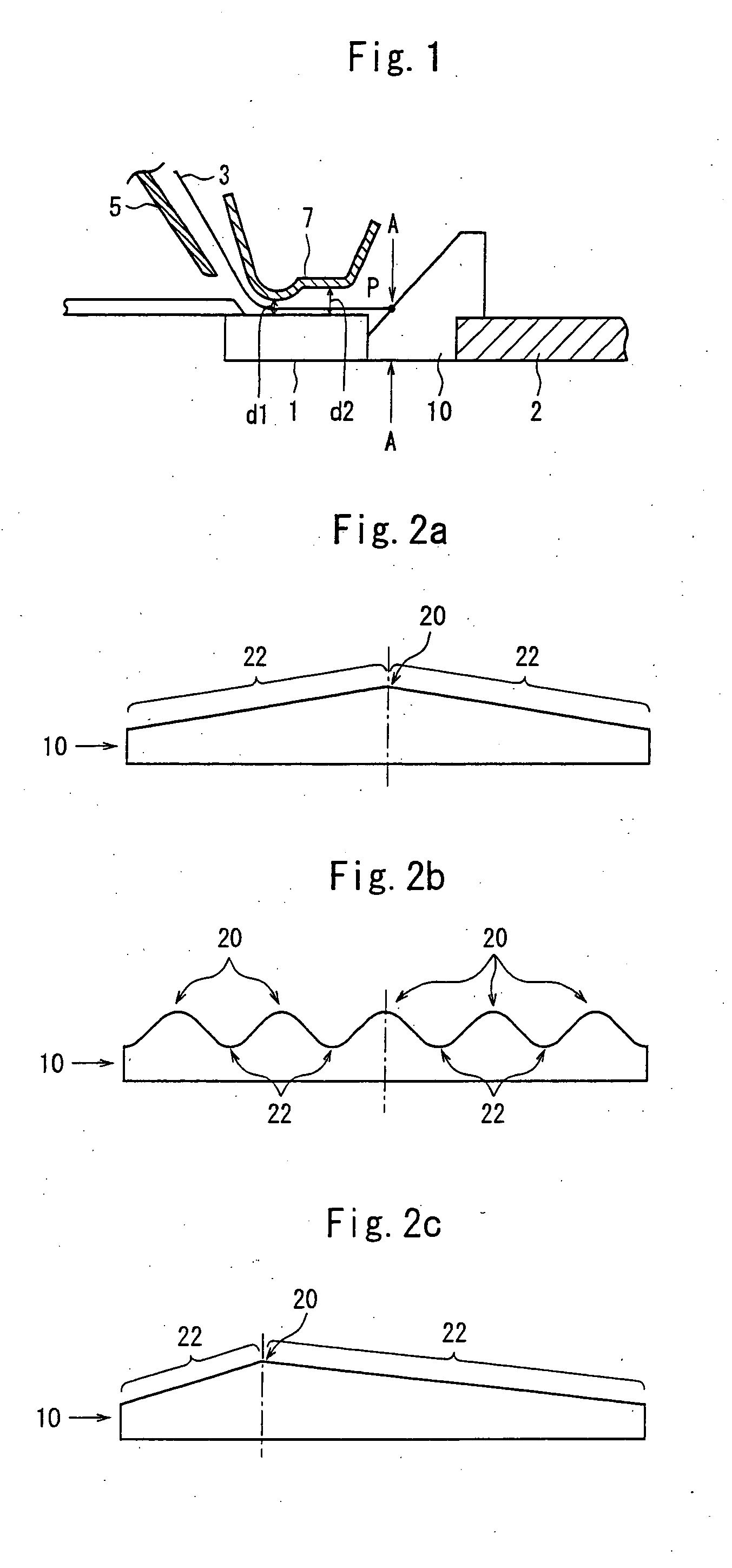
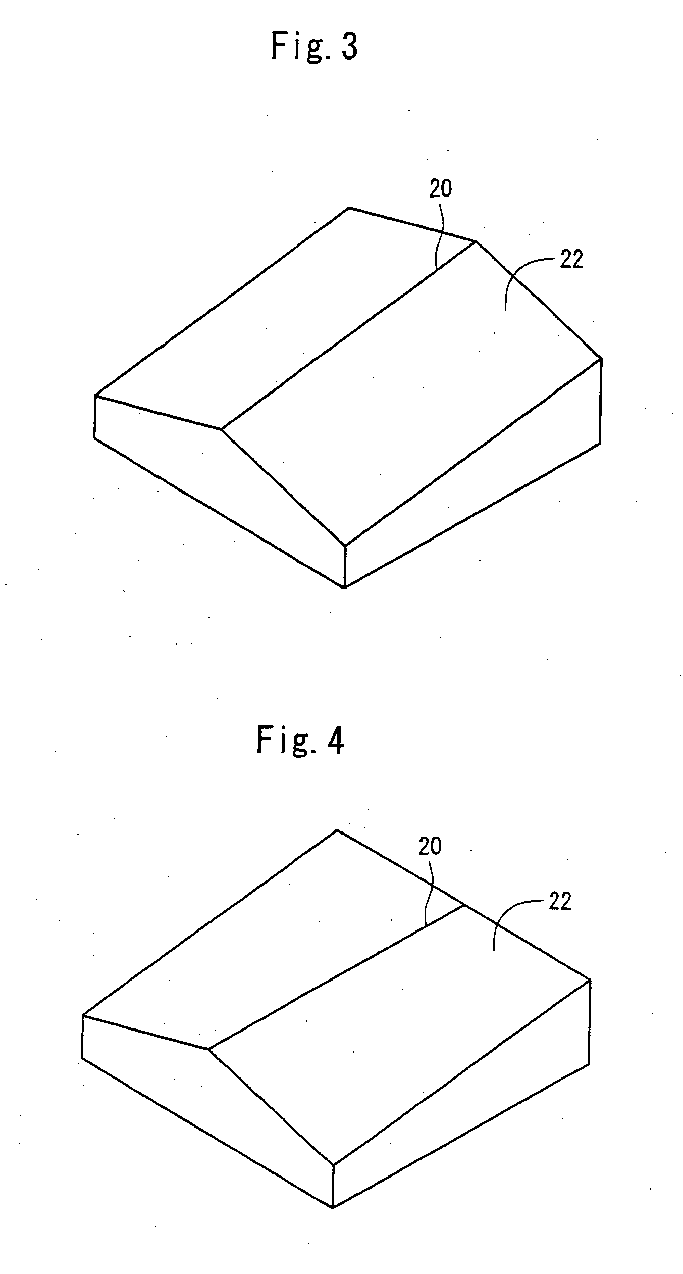
[0012] said partial guide surface is forming an inclined surface which is low at an end thereof on the side of the contact glass and becomes high as it goes away from the contact glass, and said inclined surface is relatively higher than the non-guide surfaces, permitting the manuscript discharged from the contact glass plate to come into contact with said partial guide surface and, further, permitting the manuscript to be guided upward along said partial guide surface.
[0013] In the present invention, an end of the manuscript discharged from the contact glass plate is, first, introduced onto a partial guide surface on the upper surface of the manuscript conveyer guide. That is, the end of the manuscript partly comes in contact with the guide surface of the partial guide surface and is guided upward along the partial guide surface. Namely, the whole end of the manuscript does not come in contact at one time with the manuscript conveyer guide. Therefore, the shock is small when the end of the manuscript comes in contact therewith, effectively suppressing the occurrence of unevenness in the reading of the manuscript. That is, in the conventional manuscript conveyer guide, the upper surface as a whole works as a guide surface, and the whole end of the manuscript discharged from the contact glass comes in contact with the guide surface at one time. As a result, the shock is great when the end of the manuscript comes in contact with the guide surface. When the end of the manuscript comes in contact with the guide surface, therefore, the speed of the manuscript passing on the contact glass becomes uneven causing unevenness in the reading operation. The present invention effectively suppresses the unevenness in the reading caused by the shocks.

Problems solved by technology

When the conveyer guide (hereinafter often referred to as downstream conveyer guide) is provided neighboring the contact glass plate on the manuscript discharge side, however, there arouses a problem in that the manuscript is not evenly read out.

Method used


Image

  • Manuscript conveyor guide used for a manuscript reader unit
  • Manuscript conveyor guide used for a manuscript reader unit
  • Manuscript conveyor guide used for a manuscript reader unit

Examples


Embodiment Construction

[0017]FIG. 1 is a side sectional view schematically illustrating the arrangement of a manuscript conveyer guide according to the present invention. In FIG. 1, a contact glass 1 is mounted on a machine frame 2 on the upper surface of a predetermined image-forming apparatus, and a manuscript 3 that is to be read out for its images passes on the upper surface of the contact glass 1. That is, though not illustrated, an optical unit comprising a source of light, a CCD element and an optical lens is arranged on the lower side of the contact glass 1, and the manuscript passing on the contact glass 1 is irradiated with light to read the image of the manuscript.

[0018] Namely, an upstream conveyer guide 5 is arranged over the contact glass 1 on the upstream side relative to the direction in which the manuscript 3 is conveyed, an upper guide 7 is arranged over the contact glass 1 maintaining a suitable distance, the manuscript plated on a predetermined manuscript plate (not shown) is conveyed...


PUM


Abstract

A manuscript conveyer guide which has a curved surface and a flat surface in a facing portion to an upper surface of the contact glass plate, the curved surface being positioned on the upstream in the manuscript conveying direction, the flat surface being positioned on the downstream in the manuscript conveying direction, and the distance d2 between the flat surface and the contact glass being greater than the distance d1 between the curved surface and the contact glass. The manuscript conveyor guide is arranged over the contact glass plate and guides the manuscript that has passed over the contact glass plate in a direction of discharge.

Description

CROSS REFERENCE TO RELATED APPLICATIONS [0001] This is a divisional of application Ser. No. 10 / 831,122, filed Apr. 26, 2004.BACKGROUND OF THE INVENTION [0002] 1. Field of the Invention [0003] The present invention relates to a manuscript conveyer guide used for a manuscript reader unit in image-forming machines such as a copier, a facsimile, a printer and a scanner. More specifically, the invention relates to a member used as a guide for conveying a manuscript, that is placed adjacent to a contact glass plate and for guiding the manuscript discharged from the contact glass plate at the time when the manuscript moving on the contact glass plate is read out by using an optical system arranged under the contact glass plate. [0004] 2. Description of the Related Art [0005] In the image-forming apparatus based on the electrophotographic method, the surface of the photosensitive material is uniformly charged to a predetermined polarity, an electrostatic image is formed by being exposed to ...

Claims


Application Information

Patent Timeline
Patent Type & Authority Applications(United States)
IPC IPC(8): H04N1/04B65H5/38G03G15/00G06T1/00H04N1/00
CPCG03G15/602G03G2215/00189
Inventor TSUCHIYA, HIROAKI
Owner TSUCHIYA HIROAKI
Learn More