Sound source separation apparatus and sound source separation method

a separation apparatus and sound source technology, applied in the field of sound source separation apparatus and sound source separation method, can solve the problems of increasing operation load, reducing the number and consuming a lot of time, so as to achieve reduce the number of times of sequential calculations necessary to converge the separating matrix. , the effect of high sound source separation performan

Inactive Publication Date: 2007-06-14
KOBE STEEL LTD
View PDF0 Cites 28 Cited by
  • Summary
  • Abstract
  • Description
  • Claims
  • Application Information

AI Technical Summary

Benefits of technology

[0021] On the other hand, while the sound source separation processing is executed, if a result that a degree of correlation among the separated signals exceeds the predetermined level is obtained by the second correlation evaluation processing, it is assumed that the learning calculation of the separating matrix results in a local solution due to a change of the status of the acoustic space (status of the sound source). In such a case, if the separating matrix initialization processing is performed, an (high sound source separation performance) initial matrix corresponding to a new status of the acoustic space can be determined again. As a result, it can be prevented that the learned result of the separating matrix results in the local solution if the change in the acoustic environment is changed, and the sound source separation performance can be increased as much as possible.
[0022] According to the present invention, a certain time after the start of the processing or if an acoustic environment is changed (a sound source is moved, added or changed, etc.), the initial matrix (the separating matrix to which the initial value of the learning calculation start is set) corresponding to the acoustic environment status can be given. Accordingly, while the number of times of sequential calculations necessary to converge the separating matrix can be reduced, it can be prevented that the learned result of the separating matrix resulting in a local solution. As a result, while the operation load of the separating matrix is reduced, the sound source separation performance can be increased as much as possible and thus, suitable for real time sound source separation.

Problems solved by technology

Then, the operation load increases and if the calculation is carried out by a practical processor, it takes severalfold of time as compared with a time length of mixed sound signals to be input.
As a result, even if real time processing of the sound source separation processing itself is possible, the update cycle (learning cycle) of the separating matrix used for the sound source separation processing becomes long and it is not possible to immediately respond to a change of acoustic environment.
Especially, for a certain time after the start of the processing or in a case in which an acoustic environment is changed (sound source is moved, sound source is added or changed, etc.), a separating matrix (that is, initial matrix) at the time of learning calculation start is not suited for the state of the sound source at the time.
Accordingly, even if the learning calculation is converged, the sufficient sound source separation performance may not be obtained.

Method used


Image

  • Sound source separation apparatus and sound source separation method
  • Sound source separation apparatus and sound source separation method
  • Sound source separation apparatus and sound source separation method

Examples


first embodiment (see figs.1 and 2)

First Embodiment (See FIGS. 1 and 2)

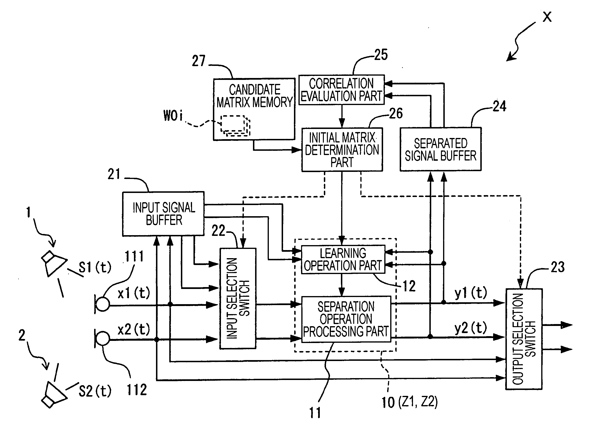
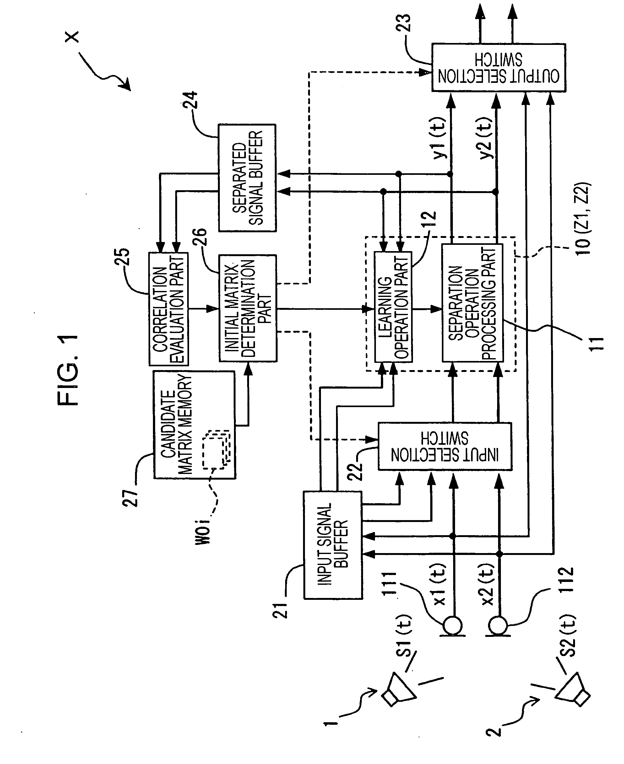
[0043] With reference to a block diagram shown FIG. 1, a sound source separation apparatus X according to an embodiment of the present invention is described.

[0044] The sound source separation apparatus X, in a state that a plurality of sound sources 1 and 2 and a plurality of microphones 111 and 112 (sound input means) exist in an acoustic space, from a plurality of mixed sound signals xi(t) which are overlapped sound source signals (individual sound signals) sequentially input from each of the sound sources 1 and 2 through each of the microphones 111 and 112, sequentially generates separated signals (that is, identified signals corresponding to the sound source signals) y which are separated (identified) sound source signals (individual sound signals) and outputs to a speaker (sound output means) in real time. The sound source separation apparatus X is applicable, for example, to a hands-free telephone, a sound collecting device for teleconfere...


PUM


Abstract

A sound source separation apparatus performs a temporary learning processing and a temporary separation processing with respect to each of a plurality of candidate matrixes (separating matrixes obtained by learning calculation based on input signals of different sound source conditions) stored on a candidate matrix memory in advance. The apparatus determines an initial matrix of the separating matrix based on the obtained correlation evaluation of the separated signals. The learning calculations of the initial matrix determination processing and separating matrix based on the initial matrix are performed at a time of the sound source separation processing by the apparatus and when a degree of correlation among the separated signals by a correlation evaluation part exceeds a predetermined level.

Description

BACKGROUND OF THE INVENTION [0001] 1. Field of the Invention [0002] The present invention relates to a sound source separation apparatus and a sound source separation method. [0003] 2. Description of the Related Art [0004] In a space where a plurality of sound sources and a plurality of microphones (sound input means) exist, to each microphone, sound signals (hereinafter, referred to as mixed sound signals) which are overlapped individual sound signals (hereinafter, referred to as sound source signals) from the plurality of sound sources are input. A method of sound source separation processing which identifies (separates) each of the sound source signals based on only thus input plurality of mixed sound signals is referred to as a Blind Source Separation Method (hereinafter, referred to as a BSS method). [0005] Further, one of sound source separation processing of the BSS method, there is a sound source separation processing based on an Independent Component Analysis (hereinafter, ...

Claims


Application Information

Patent Timeline
Patent Type & Authority Applications(United States)
IPC IPC(8): H04R5/00G10L21/028
CPCG10L21/0272
Inventor HASHIMOTO, HIROSHIHIEKATA, TAKASHIMORITA, TAKASHIIKEDA, YOHEI
Owner KOBE STEEL LTD
Why Eureka
Try Eureka