
Light-controlling element for a camera

Inactive Publication Date: 2007-06-14
SONY ERICSSON MOBILE COMM AB
View PDF8 Cites 110 Cited by
  • Summary
  • Abstract
  • Description
  • Claims
  • Application Information

AI Technical Summary

Benefits of technology

[0014] Some embodiments of the invention provide for good image quality of a camera, compared to a camera not having a mechanical component such as a mechanical variable iris.
[0015] It is an advantage with embodiments of the invention that a variable aperture stop can be provided without the need for a separate mechanical component such as, e.g., the mechanical variable iris. Thus, the required space of the variable aperture stop is reduced.

Problems solved by technology

However, although the mechanical variable iris may provide for relatively good image quality, the mechanical variable iris is a relatively bulky mechanical component that may require considerable space.
Furthermore, variable irises of the above type are most often not perfectly circular.
This may potentially result in an unwanted diffraction phenomenon due to, e.g., sharp edges of the iris.
The integration of the camera into the portable communication device generally makes the design of the portable communication device more complex.
Therefore, due to the limited space of a portable communication device, a camera in a portable communication device cannot have a bulky mechanical component such as the mechanical variable iris for providing the variable aperture stop.
The quality of images taken by a camera not having a mechanical variable iris may however be deteriorated, compared to the quality of images taken by a camera having a mechanical variable iris.
This may be inconvenient for users of a camera not having a mechanical variable iris who still demand good image quality of images taken by the camera.

Method used


Image

  • Light-controlling element for a camera
  • Light-controlling element for a camera
  • Light-controlling element for a camera

Examples


Embodiment Construction

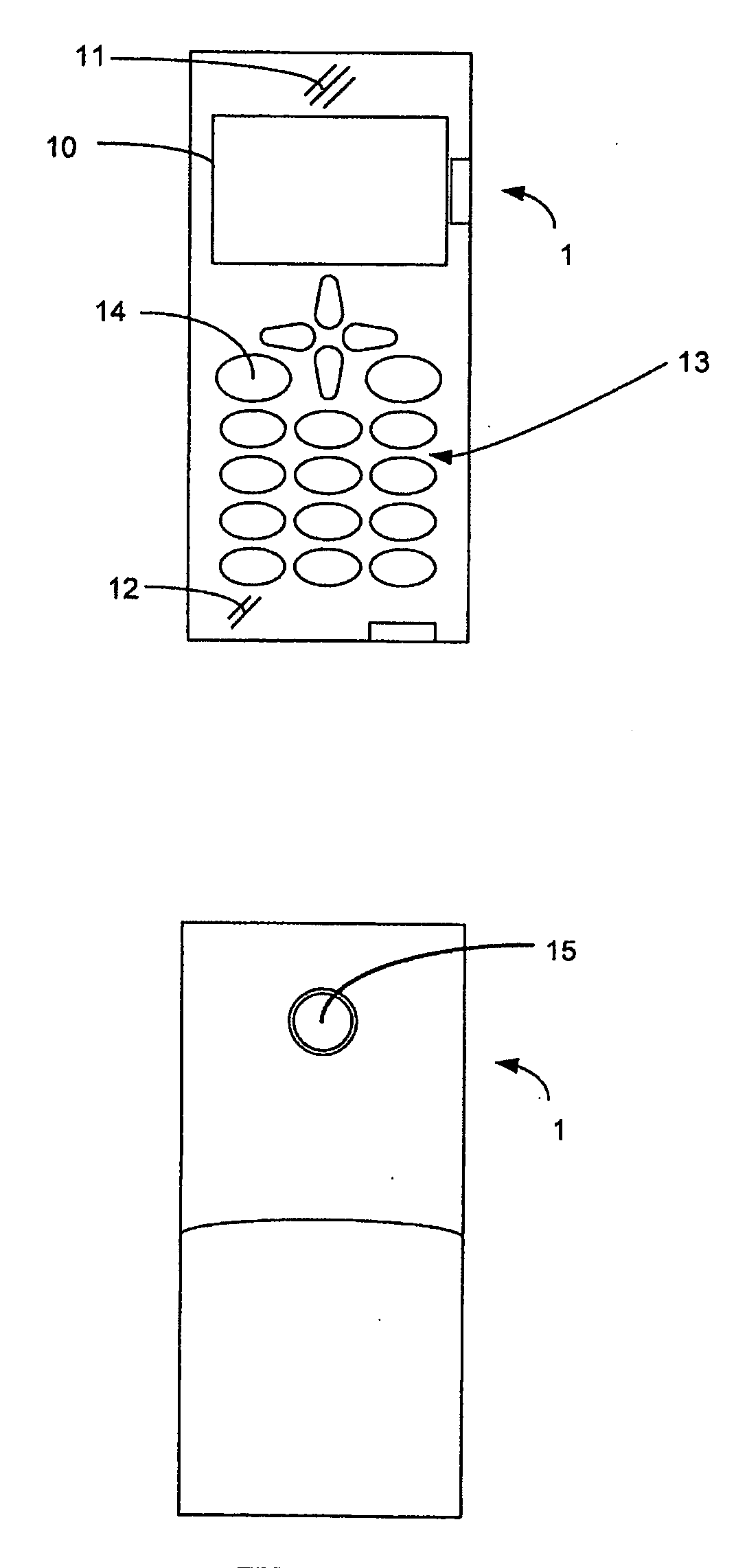
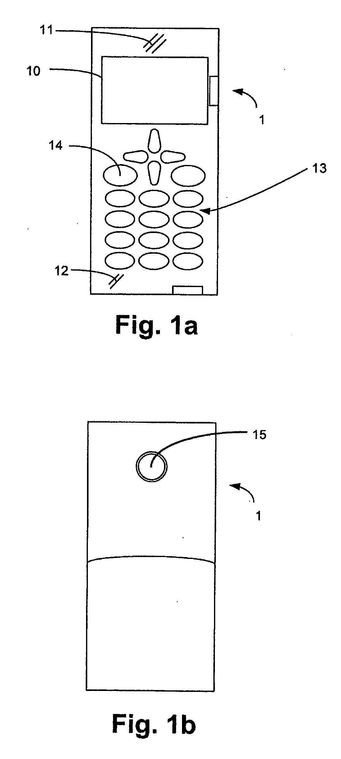
[0024] Specific embodiments of the invention will now be described with reference to the accompanying drawings. The present invention may, however, be embodied in many different forms and should not be construed as limited to the embodiments set forth herein. Rather, these embodiments are provided so that this disclosure will be thorough and complete, and will fully convey the scope of the invention to those skilled in the art. The terminology used in the detailed description of the particular embodiments illustrated in the accompanying drawings is not intended to be limiting of the invention. In the drawings, like numbers refer to like elements.

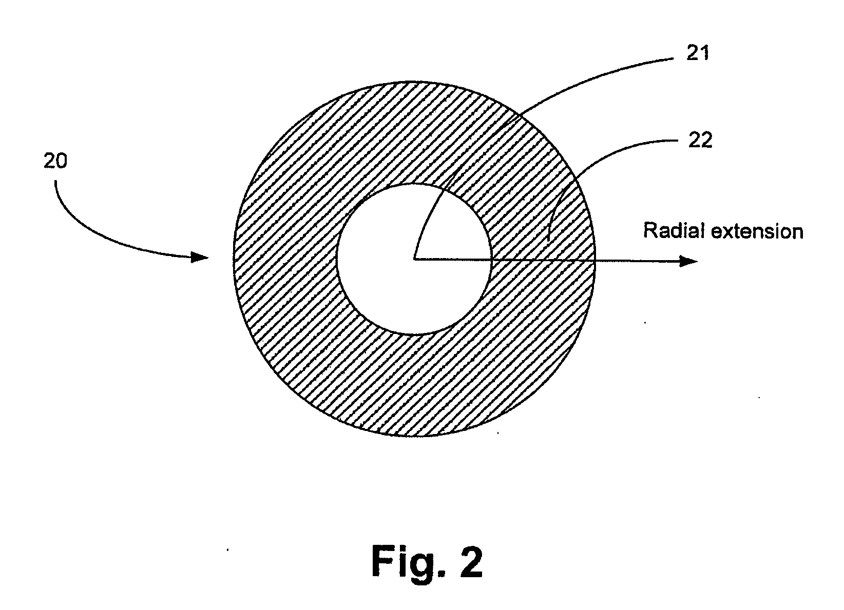
[0025] Embodiments of the invention provide a light-controlling element 20, 30a, 30b for a camera, and a method and a computer program product for admitting light to pass through such light-controlling element 20, 30a, 30b. According to embodiments of the invention, the light-controlling element 20, 30a, 30b comprises a first zone for admit...


PUM


Abstract

A light-controlling element for a camera, and a method and computer program product for admitting light to pass through such light-controlling element. The light-controlling element comprises a first zone and a second zone. The first zone is configured to admit light to pass through the light-controlling element. Furthermore, the second zone has a transmittance, which is controllable for adjusting the area of the first zone.

Description

RELATED APPLICATIONS [0001] This application claims priority under 35 U.S.C. § 119 based on U.S. Provisional Application Ser. No. 60 / 750,033, filed Dec. 14, 2005, the disclosure of which is incorporated herein by reference.TECHNICAL FIELD OF THE INVENTION [0002] The present invention relates to a light-controlling element for a camera. The light-controlling element comprises a first zone for admitting light to pass through the light-controlling element, and a second zone having a transmittance, which is controllable for adjusting the area of the first zone. The invention also relates to a method and a computer program product for admitting light to pass through such light-controlling element. DESCRIPTION OF RELATED ART [0003] In a camera, the depth of field can in general be varied by varying the radius of an aperture stop and thereby regulating the diameter of the opening of the light path through the camera. For example, a smaller radius of the aperture stop gives a longer depth o...

Claims


Application Information

Patent Timeline
IPC IPC(8): G03B9/02
CPCG02B5/23G02F1/163H04N5/2254H04N5/235H04N23/70
Inventor TRAFF, MATILDA
Owner SONY ERICSSON MOBILE COMM AB
Learn More