Image forming apparatus and method for controlling the same

Inactive Publication Date: 2007-06-14
CANON KK
View PDF4 Cites 25 Cited by
  • Summary
  • Abstract
  • Description
  • Claims
  • Application Information

AI Technical Summary

Benefits of technology

[0010] According to the present invention, the performing time interval for the image density control in the first image forming mode is different from the performing time interval for the image density control in the second image fo

Problems solved by technology

However, if the image density control is performed for all of many image forming mod

Method used


Image

  • Image forming apparatus and method for controlling the same
  • Image forming apparatus and method for controlling the same
  • Image forming apparatus and method for controlling the same

Examples


first embodiment

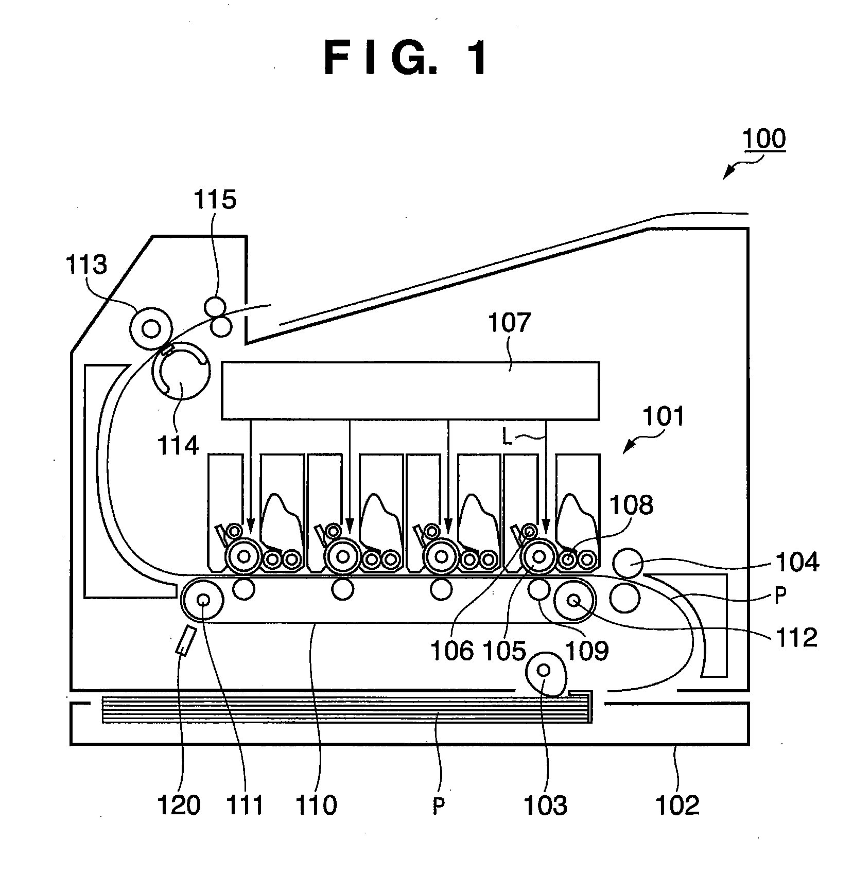
[0037]FIG. 1 is a schematic cross-sectional view of an image forming apparatus according to an embodiment. In a multi-color image forming apparatus 100, an electrophotographic method is adopted in an image forming part 101. It should be noted that image forming apparatuses are realized as a printing apparatus, a printer, a copier, a multi-functional machine, or a facsimile, for example.

[0038] A plurality of recording materials P are held in a recording material cassette 102. A paper feed roller 103 feeds the recording materials P by picking them up one by one from the recording material cassette 102. The recording material also may be called a recording medium, paper, a sheet, a transfer material, or transfer paper. The fed recording material P is transported up to a registration roller pair 104. Then, the recording material P is carried by the registration roller pair 104 to the image forming part 101 at a predetermined timing.

[0039] Herein, the image forming part 101 is constitu...

second embodiment

[0100] In the first embodiment, with respect to the image density control that was to be performed for each of a plurality of image forming modes, the image forming modes were respectively provided with different performing time intervals, and thus the downtime and the like were improved. In the second embodiment, if the image density control is performed in one image forming mode and is not performed in the other image forming mode, it is an object of this embodiment to keep a preferable color balance in the latter image forming mode.

[0101] Herein, a user may give a command to start the image density control for each image forming mode using an operation part (not shown). For example, if the user changes the setting from “enable” image density control to “disable”, then the image density control is not performed at all until the user further changes the setting to “enable”. In this case, the performing time interval for the image density control may be inappropriately long. More s...

third embodiment

[0112] Generally, image forming apparatuses have a plurality of operation modes with respectively different processing speeds. Examples of the operation modes include a normal mode for performing standard printing, and a lower speed mode with a lower processing speed than that in the normal mode. The lower speed mode is used when performing printing on an OHT (overhead transparency) sheet or on cardboard.

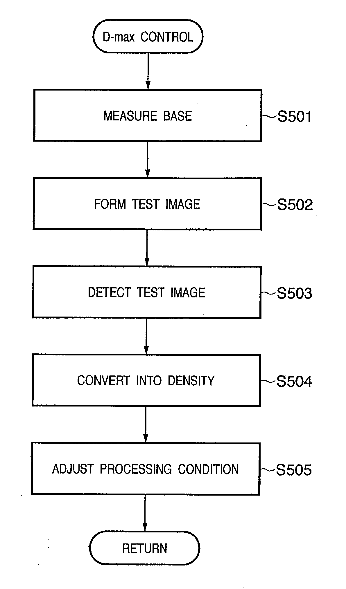
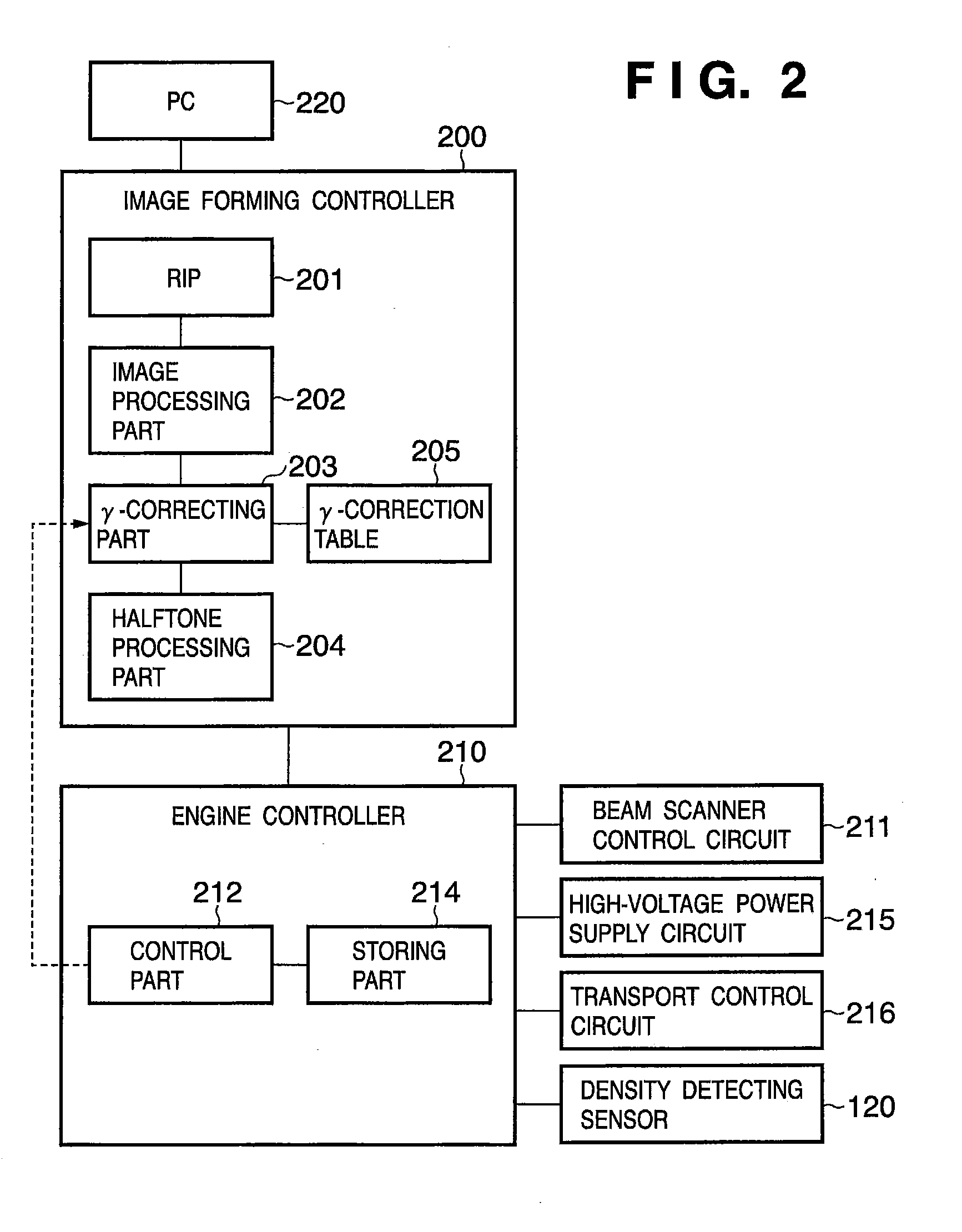
[0113] In image forming apparatuses, the image forming density and the character width, for example, may deviate from desired values depending on factors such as the usage environment. In order to address this deviation, a method has been proposed in which based on the density of a patch image formed on the intermediate transfer belt or the like, the correspondence between image forming parameters (conditions such as the charge bias, the developing bias, and the transfer bias) and the image forming density is adjusted (Japanese Patent Application Laid-Open No. 2001-343867 and 2002-...


PUM


Abstract

An image forming apparatus comprises an image forming part and a density calibration control part. The image forming part forms an image in any one of a plurality of image forming modes with respectively different processing speeds. The density calibration control part performs image density control for the image forming part in a state where any one of the plurality of image forming modes is applied. Herein, the density calibration control part makes a performing time interval for the image density control in a first image forming mode and a performing time interval for the image density control in a second image forming mode different from each other.

Description

BACKGROUND OF THE INVENTION [0001] 1. Field of the Invention [0002] The present invention relates to an image forming apparatus and a method for controlling the same. [0003] 2. Description of the Related Art [0004] Generally, in image forming apparatuses using an electrophotographic image forming process, the image density tends to fluctuate depending on various conditions such as the usage environment and the number of pages printed. In particular, in color image forming apparatuses that perform color printing by superimposing toner images with a plurality of colors, fluctuations in the image density of various colors also causes fluctuations the color balance (so-called tint). [0005] Thus, in recent years, Japanese Patent Application Laid-open No. 11-65237 proposed a color image forming apparatuses in which the amount of toner of a test image that is formed on an image carrier or the like is detected, and the image density is controlled based on the detection results. [0006] Image...

Claims


Application Information

Patent Timeline
IPC IPC(8): G03G15/00
CPCG03G15/50G03G2215/00029G03G15/0194G03G15/0189G03G2215/00949
Inventor SUZUKI, TAKEHIKONAKAGAWA, KEN
Owner CANON KK
Why Eureka
Try Eureka