Speed-regulated pressure exchanger

a technology of pressure exchanger and speed regulation, which is applied in the direction of machine/engine, hot gas positive displacement engine plant, pump components, etc., can solve the problems of complex method of setting rotor, automatic setting of rotational speed at an undefined, arrangement, sealing and design of separation elements and respective seating faces, etc., to achieve minimal mixing losses, large operating range, and efficient operation state

Inactive Publication Date: 2007-06-21
KSB AG
View PDF4 Cites 61 Cited by
  • Summary
  • Abstract
  • Description
  • Claims
  • Application Information

AI Technical Summary

Benefits of technology

[0007] A further object of the invention is to provide a rotary pressure exchanger which operates with minimal mixing losses in the rotor channels during pressure exchange.
[0008] It is also an object of the invention to provide a pressure exchanger which maintains an efficient operating state with minimal mixing losses over a large operating range with variable mass flows.
[0009] These and other objects are achieved in accordance with the present invention by providing a pressure exchanger for transferring pressure energy from a high pressure liquid of a first liquid system to a low pressure liquid of a second liquid system comprising a housing with inlet and outlet connection openings for each liquid and a rotor arranged in the housing for rotation about a longitudinal axis, the rotor having a plurality of continuous channels arranged around the longitudinal axis with openings on each rotor end face such that the rotor channels are connected with the inlet and outlet connection openings through flow openings in the housing so that during the rotation of the rotor the channels alternately carry high pressure liquid and low pressure liquid from the respective liquid systems; in which a predominantly axially extending flow transition is formed between the flow openings in the housing and the openings of the rotor channels; the flow openings in the housing are parts of arcuately shaped cavities communicating with the connection openings, and each cavity simultaneously covers a plurality of rotor channel openings and has a contour that smoothes out the velocity of flow in the area of the housing flow openings; the rotor has an outside surface contour that converts or transfers energy such that a partial liquid stream impinging with high pressure energy or flow energy against the rotor contour causes the rotor to rotate, and a regulator varies the amount of the partial stream and the rotational speed of the rotor and adjusts the rotor speed to a speed suitable for essentially shock-free admission of the liquid flow into the rotor channels.
[0010] In accordance with the present invention, the cavities have a construction which makes the velocity of flow uniform in the area of the flow opening in the housing; the outside surface of the rotor has a shape which converts energy and / or transmits energy; a partial stream of a high pressure energy and / or flow energy striking this shape generates the rotor rotational speed, and a regulator alters the quantity of the partial stream and the rotational speed of the rotor and regulates the rotor speed at a rotational speed for essentially shock-free admission of the mass flow into the rotor channels. With this approach it is easily possible to take a partial stream from the total mass flow flowing to a pressure exchanger in a plant and with the help of this partial stream to generate a certain drive torque for the rotor. This advantageously facilitates a startup procedure of the rotor. Furthermore, this approach offers an opportunity to create a permanent and regulated torque as the driving momentum for continuous operation of the rotor with the help of the partial stream, the amount of which is adjustable. Thus, in the respective operating state, the rotational speed of the rotor is adapted to the prevailing plant conditions through appropriate variation of the partial stream.
[0011] Due to the cavities arranged in the housing with their flow-smoothing contour, i.e., the design, shape and course of the wall surfaces surrounding the cavity, a uniform velocity profile of the main stream is established in transition to the rotor and in front of the openings in the rotor channels receiving the oncoming flow in the area of the flow opening in the housing. This is the mass flow of the main stream reduced by the partial stream. The direct drive of the rotor by the partial stream and the development of a uniform velocity profile in the flow opening in the housing yield the advantage that the main stream reaches the rotor channels essentially shock-free. And if a change in the mass flow is also established because of altered plant conditions at the pressure exchanger, i.e., there is a change in mass flow toward a higher or lower flow rate, then there is an adjustment of the rotor speed with a suitably modified partial stream to continue to ensure a substantially shock-free oncoming flow of the main stream is admitted to the rotor channels.
[0012] And a uniform velocity profile of the channel flow situated therein is also established in the cross section of the rotor channels due to the uniform flow distribution of the main stream upstream from the openings of the rotor channels. As a result of this, this yields a smaller and more stable mixing zone in the area between the two liquids with their different properties within the rotor channels. This improves the efficiency of such a pressure exchanger and a plant which is influenced thereby. The partial stream used for driving the rotor flows out into a lower pressure zone within the pressure exchanger, i.e., in this case into the second liquid system.

Problems solved by technology

To start operation thereof with such a pressure exchanger, a complex method is necessary to set the rotor in rotation.
It is a disadvantage here that this rotational speed is automatically established at an undefined rotational speed value as a function of altered plant conditions on the high pressure side and the low pressure side.
However, disadvantages here include the arrangement, sealing and design of the separation element and the respective seating faces.
In addition, a complex high-pressure gasket is necessary as a shaft seal in the area of a shaft bushing for the external drive.

Method used


Image

  • Speed-regulated pressure exchanger
  • Speed-regulated pressure exchanger
  • Speed-regulated pressure exchanger

Examples


Embodiment Construction

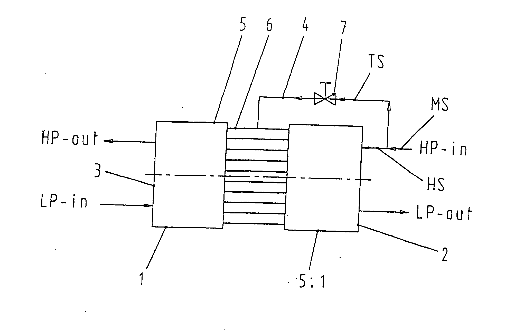
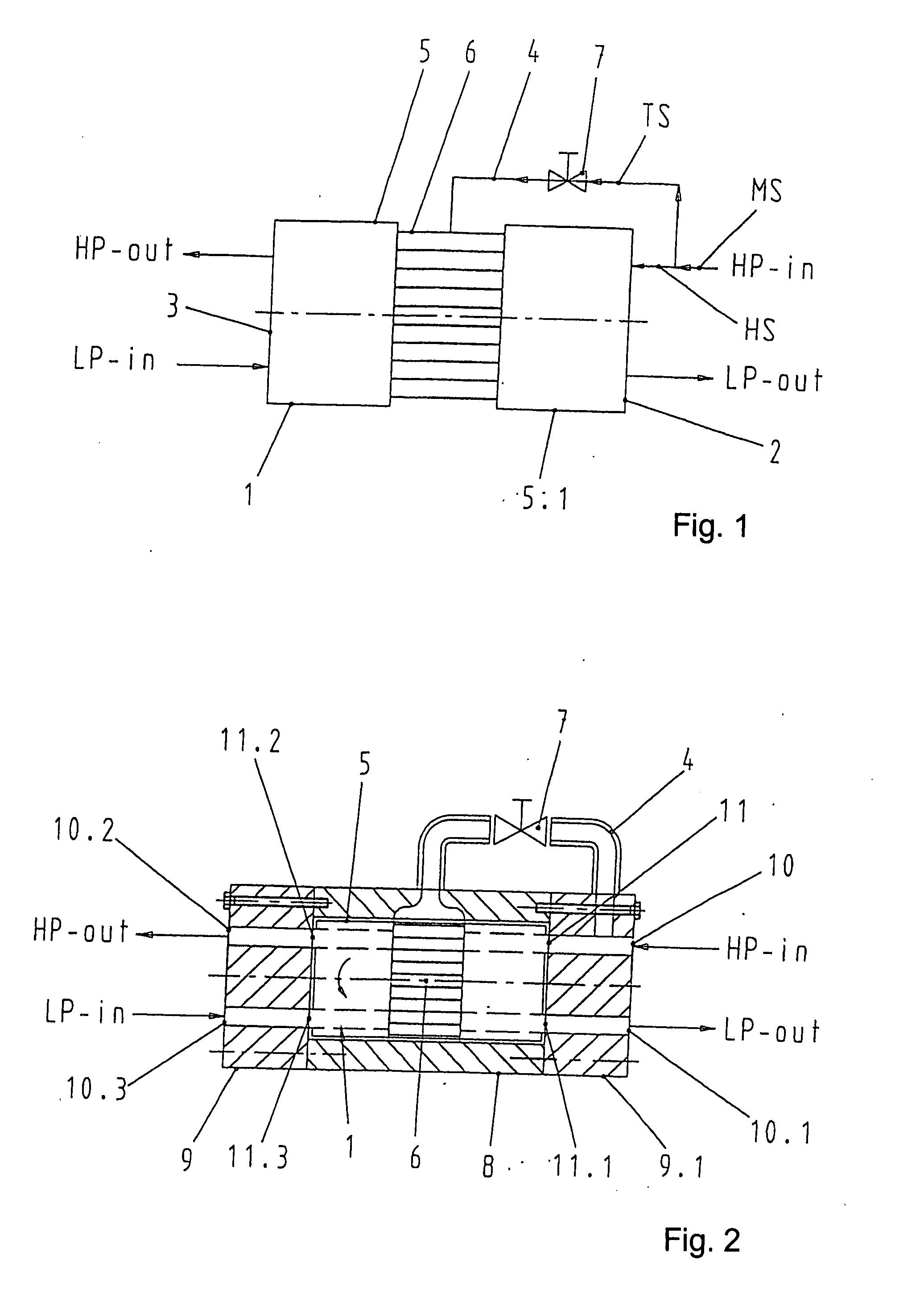
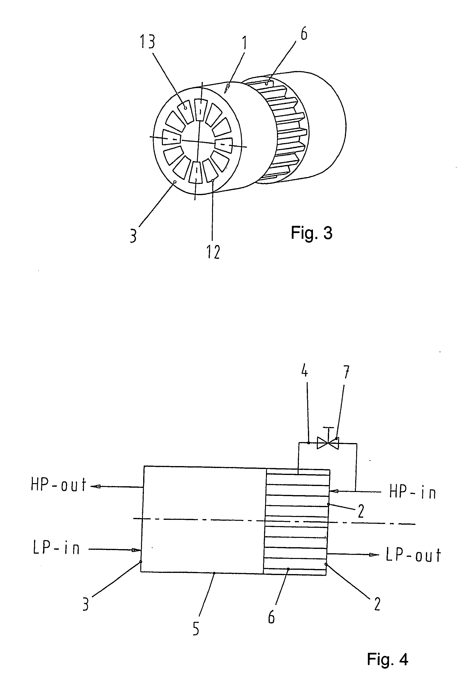
[0033]FIG. 1 shows a cylindrical rotor 1 of a pressure exchanger. It is shown in a view from above with the axis of rotation line in the plane of the drawing and, for reasons of simplicity, the other housing parts which surround the rotor and in which the flow guides are arranged have been omitted. The arrows represent the directions of flow and the various liquids which are in operative connection with the rotor. On a rotor end face 2, the arrow HP-in indicates the direction of flow of a first liquid having a high pressure that is to be transferred to a second liquid LP-in flowing into the rotor 1 on the other rotor end face 3. After the transfer of pressure from HP-in to LP-in, which takes place in the pressure exchanger due to the rotation of rotor 1, a liquid whose pressure has been increased flows out of the pressure exchanger as HP-out on the rotor end face 3 and flows back to a plant. On the rotor end face 2, which is on the right here, an arrow LP-out pointing away from the ...


PUM


Abstract

A pressure exchanger for transferring pressure from a higher pressure liquid in a first liquid system to a lower pressure liquid in a second liquid system having a housing (8) with inlet and outlet connection openings (10-10.3) for each liquid and a rotor (1) arranged in the housing for rotation about a longitudinal axis. The rotor has a plurality of through channels (13) arranged around the longitudinal axis with openings (12) on axial end faces (2, 3) of the rotor. The rotor channels (13) are connected to the connection openings (10-10.3) through flow openings (11-11.3) in the housing such that during rotation of the rotor high pressure liquid and low pressure liquid are alternately supplied to the respective systems. A predominantly axially extending flow transition is formed between the flow openings (11-11.3) in the housing and the openings (12) of the rotor channels (13), and the flow openings in the housing form part of curved cavities (19) with each cavity (19) simultaneously covering several rotor channel openings (12) and having a shape which equilibrates the liquid flow speed in the vicinity of the housing flow openings (11-11.3). External surfaces (5-5.3) of the rotor (1) have an energy converting or energy transmitting configuration (6), and a partial flow (TS) of high pressure and/or flow energy impinging on the configuration (6) produces rotation of the rotor (1). A regulator (7) the varies the amount of the partial flow (TS) and the rotational speed of the rotor (1) and controls the rotational speed of the rotor for substantially shock-free admission of the mass flow into the rotor channels (13).

Description

CROSS REFERENCE TO RELATED APPLICATIONS [0001] This application is a continuation of international patent application no. PCT / EP2005 / 007649, filed Jul. 14, 2005 designating the United States of America and published in German on Feb. 16, 2006 as WO 2006 / 015682, the entire disclosure of which is incorporated herein by reference. Priority is claimed based on Federal Republic of Germany patent application no. DE 10 2004 038 440.1, filed Aug. 7, 2004.BACKGROUND OF THE INVENTION [0002] The invention relates to a pressure exchanger for transferring pressure energy from a first liquid of a first liquid system to a second liquid of a second liquid system, comprising a housing having connector openings in the form of inlet and outlet openings for each liquid and a rotor arranged to rotate about its longitudinal axis within the housing, the rotor having a plurality of continuous channels with openings arranged around its longitudinal axis on each rotor end face, in which the rotor channels co...

Claims


Application Information

Patent Timeline
Patent Type & Authority Applications(United States)
IPC IPC(8): F02C3/02B01D61/06F04F99/00F04F13/00
CPCF04F13/00
Inventor BROSS, STEPHANKOCHANOWSKI, WOLFGANG
Owner KSB AG
Why Eureka
Try Eureka