Igniter gun equipped with a safety mechanism

a safety mechanism and igniter technology, applied in the direction of burners, combustion processes, lighting and heating apparatus, etc., can solve the problem that the first end of the lever cannot move the hook, and achieve the effect of reducing manipulation force, easy operation, and eliminating deficiency and drawbacks

Inactive Publication Date: 2007-07-17
SANKAI
View PDF18 Cites 9 Cited by
  • Summary
  • Abstract
  • Description
  • Claims
  • Application Information

AI Technical Summary

Benefits of technology

[0003]The present invention is provided to eliminate the deficiency and drawback in current technology and provide an easily operated igniter gun equipped with safety mechanism for gas outlet valve operation controlling, which can decrease manipulation force and control effectively the operation state of the gas outlet valve.
[0005]In normal condition (i.e. the safety state), the hook goes beyond movement range of the first end of the lever by the safety spring. Thus, even if the trigger is to be pressed down directly at this time, the first end of the lever cannot move the hook. Although the action of the trigger may produce spark, the gas outlet valve hasn't been opened, the igniter gun produces no flame, and the safety property of the igniter gun is hence greatly improved.
[0007]The igniter gun may further comprise a locker between the trigger and the controller switch. A middle portion of the locker is connected pivotally with the casing, one end of the locker abuts on the trigger, and the other end of the locker is connected with a middle portion of the controller switch by a rod. The locker may further include a movement groove for turning controller switch at a connecting position with the controller switch. The locker serves to lock the operation state of the trigger, control effectively the operation of the trigger, improve further the safety property of the igniter gun and realize a double safeguard of the igniter gun, because it can control effectively both operations of the gas outlet valve and the trigger. In time of the locker pushing upward the controller switch by the controller switch controlling, it turns around the rod and the middle portion of the locker moves within the movement groove, in this way, the hook can act within the movement range of the first end of the lever and the end of the locker abutting the trigger may get off the trigger.
[0009]The invention has the following technical effects by supplementing a lever, a gas controller and a trigger, and controlling the gas controller and the locker by the controller switch: (1) Easy, smooth, flexible and nice hand feeling operation of the trigger by lever principle; (2) In operation, the controller switch can control effectively the operation of the trigger as well as the gas outlet valve, and, thus, a double safeguard of the igniter gun is realized, thereby preventing the mistake operation, making it more difficulty for children to operate it and improving greatly the safety property of the igniter gun.

Problems solved by technology

Thus, even if the trigger is to be pressed down directly at this time, the first end of the lever cannot move the hook.

Method used


Image

  • Igniter gun equipped with a safety mechanism
  • Igniter gun equipped with a safety mechanism
  • Igniter gun equipped with a safety mechanism

Examples


embodiment 1

[0018

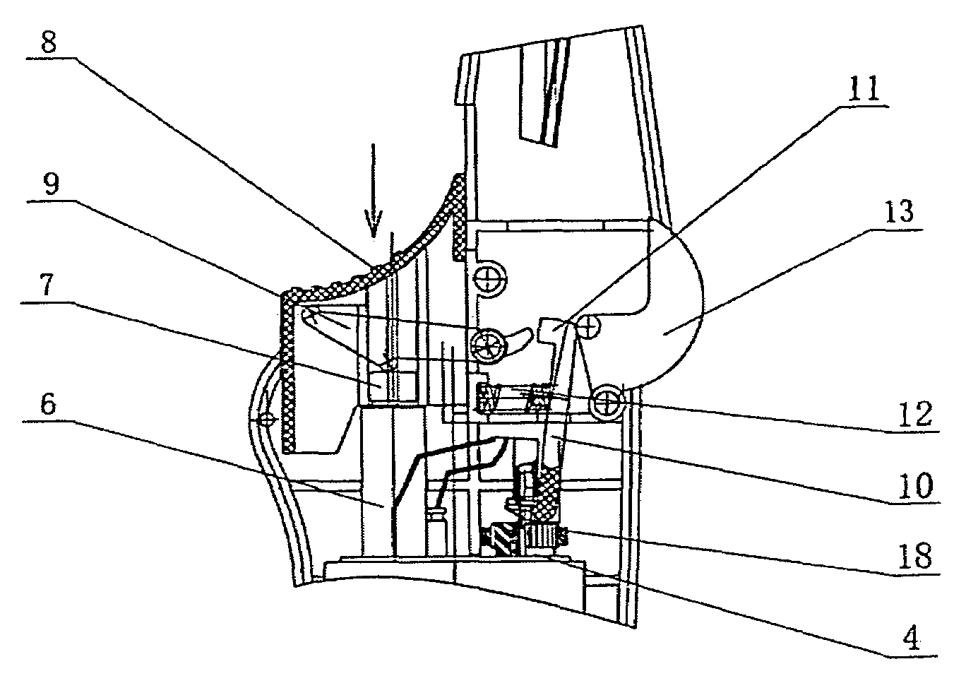
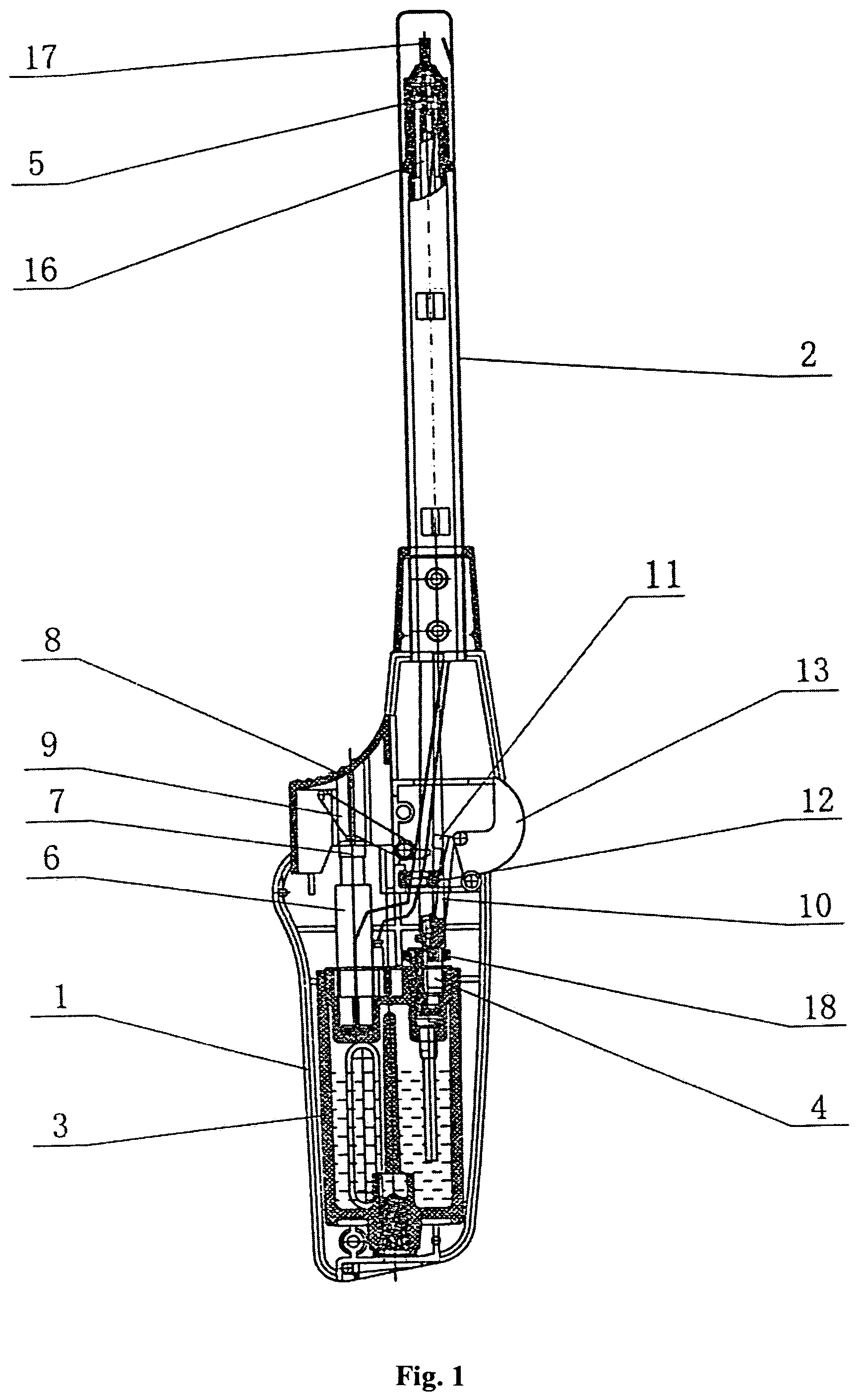
[0019]Referring to FIGS. 1-4, an igniter gun that can be operated safely and easily is provided. The igniter gun comprises casing 1, a gun tube 2 above the casing 1, a liquefied fuel container 3 within the casing 1, a gas outlet assembly and an igniting assembly above the liquefied fuel container 3

[0020]The gas outlet assembly comprises gas outlet valve 4, a gas outlet nozzle 5, a gas outlet tube 16, an igniter spring 17 and a fire adjusting ring 18. One end of the gas outlet nozzle 5 is accommodated in the gun tube 2, while the other end of the gas outlet nozzle 5 is connected with the liquefied fuel container 3 via the gas outlet valve 4.

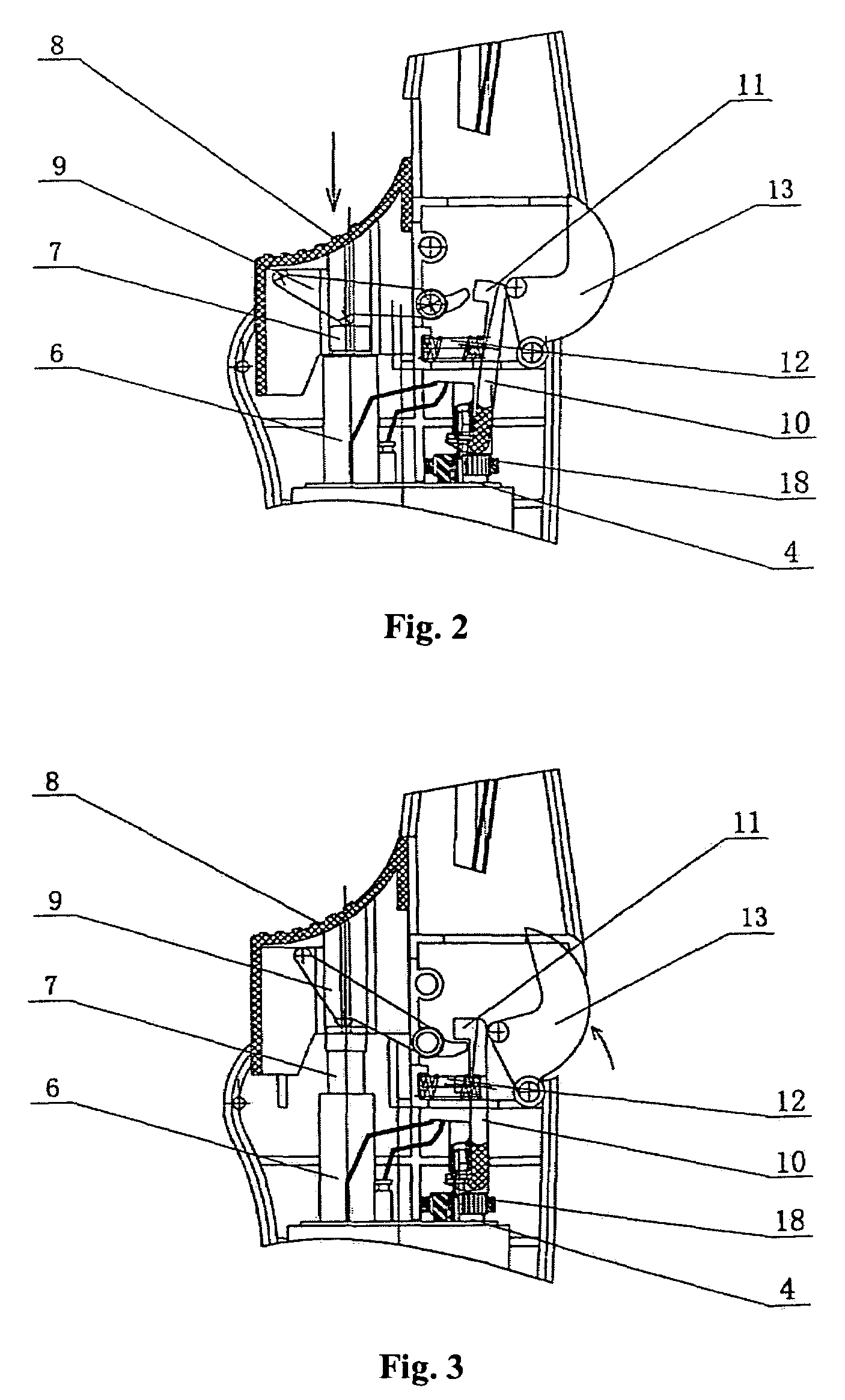
[0021]The igniting assembly comprises a piezoelectric member 6, a piezoelectrics pusher 7 and a trigger 8 above the piezoelectrics pusher 7, and a lever 9. One end of the piezoelectric member 6 is connected to the liquefied fuel container 3, while the other end of the piezoelectric member 6 is connected with one end of the trigger 8 via the p...

embodiment 2

[0026

[0027]Referring to FIGS. 5-7, embodiment 2 of the present invention includes the following differences from embodiment 1. A locker 14, of which the middle portion is connected pivotally with the casing 1, is set between the trigger 8 and the controller switch 13. The locker 14 abuts against the trigger 8. One end of the locker 14 abuts on the trigger 8, while the other end of the locker 14 is connected with the middle portion of the controller switch 13 by a rod. The locker 14 has a movement groove 15 for turning the controller switch 13 at connecting position with the controller switch 13.

[0028]In normal condition, the trigger 8 is locked by the locker 14 and the trigger cannot be pressed down. Even the locker 14 is destroyed by a great force and the trigger 8 may be pressed down to the bottom, but the hook 11 on one end of the gas controller 10 may goes beyond the movement range of the first end of the lever 9 by the safety spring 12, the first end of the lever 9 cannot move ...


PUM


Abstract

The invention is an igniter gun equipped with a safety mechanism. The invention is characterized in that a lever is provided between a piezoelectric pusher and a trigger, with a first end of the lever pivotally connected to the casing, the second end and middle portion of the lever abutting against the trigger and the piezoelectric pusher respectively; one end of a gas controller is connected with a gas outlet valve, while another end of the gas controller forms a hook that abuts against the first end of the lever, a safety spring which urges the hook to go beyond a movement range of the first end of the lever is set between one side of the gas controller and a casing, a controller switch abutting against a back of the hook is set between another side of the gas controller and the casing, the controller switch is pivotally connected to the casing, and a portion of the controller switch exposed outside the casing.

Description

FIELD OF THE INVENTION[0001]The invention relates to an igniter device, concretely relates to an easily operated igniter gun equipped with a safety mechanism.BACKGROUND OF THE INVENTION[0002]A current igniter gun is not provided with a safety mechanism, and is not restrictive to the manipulation of trigger. Thus, the current igniter is apt to be ignited to hurt children or even endanger the public safety if it is mistakenly manipulated by accident, or children playing with it accidentally knock against the trigger of the igniter gun by hard objects. Meanwhile a gas outlet valve may be opened to discharge inflammable gas if the trigger is pushed down accidentally by external force, so the production and sale of igniter gun without safety mechanism equipped have been or are going to be forbidden in some countries and areas. For this reason, an igniter gun with a safety switch (or mechanism) equipped has been developed, in which the safety switch (or mechanism) controls the course of t...

Claims


Application Information

Patent Timeline
Patent Type & Authority Patents(United States)
IPC IPC(8): F23Q2/16F23Q7/24F23Q2/28
CPCF23Q2/287
Inventor JIANG, ZHIHONG
Owner SANKAI
Why Eureka
Try Eureka