Air-conditioning apparatus

A technology of air conditioning and oil recovery, applied in space heating and ventilation, heating methods, lighting and heating equipment, etc., can solve the problems of insufficient recovery of lubricating oil, no direct disclosure or hint of lubricating oil recovery, etc., to achieve the elimination of lubricating oil The effect of insufficient oil

Inactive Publication Date: 2008-04-16
MITSUBISHI HEAVY IND THERMAL SYST
View PDF2 Cites 15 Cited by
  • Summary
  • Abstract
  • Description
  • Claims
  • Application Information

AI Technical Summary

Problems solved by technology

Therefore, in this structure, there is a problem that the lubricating oil stagnating in the indoor unit with a long refrigerant pipe length and its refrigerant circuit cannot be sufficiently recovered.
[0008] In addition, although Japanese Patent Application Laid-Open No. 2006-183979 proposes a system and method for detecting the length of a refrigerant pipe, it does not directly disclose or suggest a technology for recovering lubricating oil remaining in the refrigerant circuit to the compressor.

Method used


Image

  • Air-conditioning apparatus
  • Air-conditioning apparatus
  • Air-conditioning apparatus

Examples


no. 1 approach

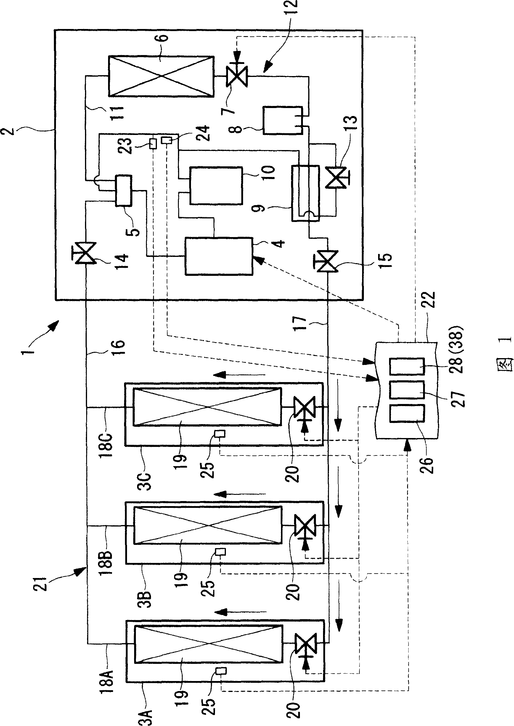
[0032] Fig. 1 shows a refrigerant circuit diagram of a combination air conditioner 1 according to a first embodiment of the present invention. The air conditioner 1 is composed of one outdoor unit 2 and a plurality of indoor units 3A, 3B, and 3C connected in parallel to the outdoor unit 2 . In addition, in this embodiment, the case where three indoor units 3A, 3B, and 3C are connected is exemplified, but the number of connected indoor units 3A, 3B, and 3C is not limited.

[0033] The outdoor unit 2 includes: a reverse-phase-driven compressor 4 for compressing refrigerant; a four-way switch valve 5 for switching the direction of refrigerant circulation; an outdoor heat exchanger 6 for exchanging heat between refrigerant and outside air; expansion valve 7; storage tank 8 for storing liquid refrigerant; subcooling heat exchanger 9 for subcooling liquid refrigerant; The accumulator 10 and the components are connected by known refrigerant pipes 11 to form a refrigerant circuit 12 ...

no. 2 approach 〕

[0061] Next use Figure 1 and Figure 3A , FIG. 3B to illustrate the second embodiment of the present invention.

[0062] This embodiment differs from the first embodiment described above in the configuration of the oil recovery control unit 38 . Other points are the same as those of the first embodiment, and thus description thereof will be omitted.

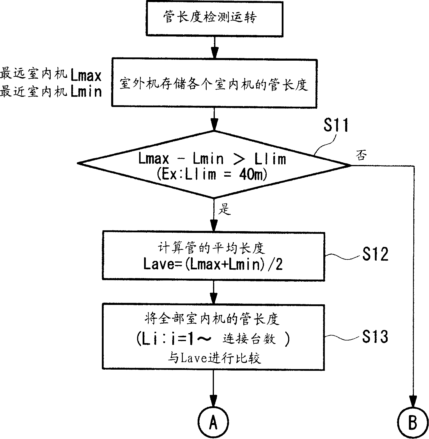
[0063] The oil recovery control unit 38 of this embodiment changes the opening degree of each indoor electronic expansion valve 20 based on the refrigerant pipe length of each indoor unit 3A, 3B, 3C instead of changing the operation time during the oil recovery operation.

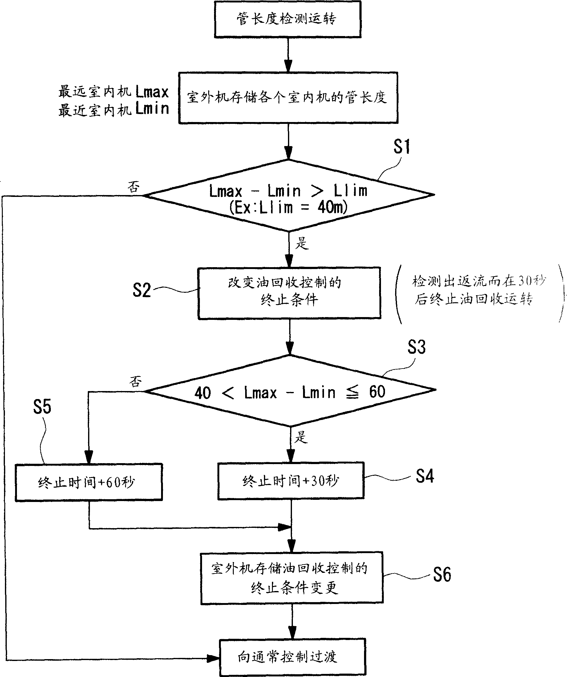
[0064] The oil recovery control unit 38 is based on Figure 3A , the control flow shown in FIG. 3B controls the opening of each indoor electronic expansion valve 20 during the oil recovery operation as follows.

[0065] Such as Figure 3A , as shown in FIG. 3B, in the oil recovery control unit 38, based on the detection result of the refrigerant tube lengt...


PUM


Abstract

An air-conditioning apparatus (1) capable of reliably recovering lubricant accumulated in indoor units (3A,3B,3C) and their refrigerant circuit, regardless of the refrigerant-pipe length differences of the indoor units connected to each other, has been desired, and includes an operating unit (22) configured to carry out liquid return at each indoor unit, to carry out an oil-recovery operation for recovering lubricant accumulated in the refrigerant circuit, and to complete the oil-recovery operation when liquid return is detected at the outdoor unit (2). The operating unit includes a detecting unit configured to detect the refrigerant pipe length of each of the indoor units, a storing unit configured to store the refrigerant pipe lengths detected by the detecting unit, and a control unit configured to change the operation time during the oil-recovery operation on the basis of the refrigerant pipe length of each of the indoor units stored in the storing unit.

Description

technical field [0001] The present invention relates to a combination type air conditioner having an oil recovery operation function of recovering lubricating oil that circulates in a refrigerant circuit together with refrigerant discharged from a compressor and remains in the refrigerant circuit to the compressor. middle. Background technique [0002] In an air conditioner using a refrigerant compression refrigeration cycle, a compressor compresses a refrigerant and circulates it in a refrigerant circuit to obtain cooling and heating effects. The compressor is filled with lubricating oil for lubricating the sliding parts, and part of the lubricating oil is discharged from the compressor to the refrigerant circuit together with the compressed refrigerant. After the lubricating oil circulates in the refrigerant circuit together with the refrigerant, it returns to the compressor again, but a part of the lubricating oil remains on the side of the refrigerant circuit. The stag...

Claims


Application Information

Patent Timeline
Patent Type & Authority Applications(China)
IPC IPC(8): F24F11/02
CPCF25B31/004F25B49/02F25B2500/01F25B2313/023F25B2600/2513F25B2500/16F25B13/00
Inventor 渡辺聪前野政司五十住晋一三苫惠介
Owner MITSUBISHI HEAVY IND THERMAL SYST
Why Eureka
Try Eureka