Automatic coating device

Inactive Publication Date: 2007-06-21
INVENTEC CORP
View PDF3 Cites 0 Cited by
  • Summary
  • Abstract
  • Description
  • Claims
  • Application Information

AI Technical Summary

Benefits of technology

[0006] In view of the foregoing, an objective of the invention is to provide an automatic coat

Problems solved by technology

Therefore, the prior method is difficult in implementing

Method used


Image

  • Automatic coating device
  • Automatic coating device
  • Automatic coating device

Examples


Example

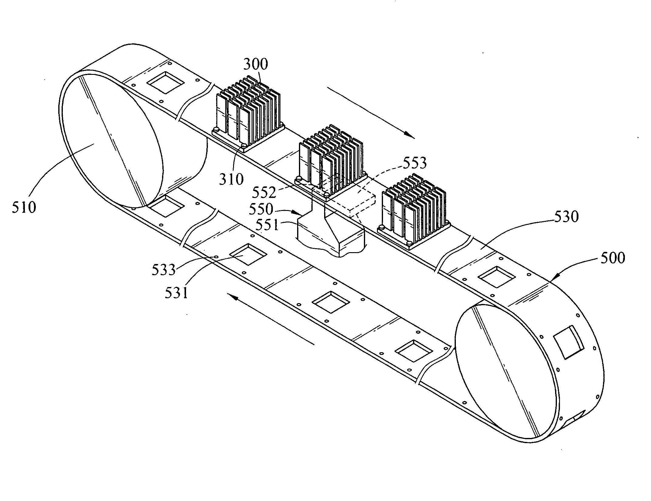
[0018] Referring to FIGS. 2, 3 and 4A, an automatic coating device 500 according to the invention can automatically coat a coating material 570 onto an object 300 to be coated, avoiding the time-consuming manual coating. As shown in FIGS. 2, 3 and 4A, the automatic coating device 500 includes a driving motor 510, a conveyer 530, and an injector 550. The driving motor 510 drives the conveyer 530 to cyclically rotate. A plurality of injection openings 531 are formed on the conveyer 530. The object 300 is disposed on one side of the conveyer 530 so that the coating area of the object 300 is exposed by one of the injection opening 531. The object 300 is temporally fixed on the conveyer 530 and driven by the conveyer 530 into motion.

[0019] The injector 550 includes a body 551 and an extension board 553. The body 551 accommodates the coating material 570. The body 551 is formed with an outlet 552, through which the coating material 570 leaves the body 551. The extension board 553 is prot...


PUM


Abstract

An automatic coating device uses a driving motor and a conveyer to form a cyclically rotating module. An injector filled with a coating material is disposed on one side of the conveyer. When an object to be coated is disposed on the other side of the moving conveyer, the coating material is then applied onto the object by the injector. This can increase the coating speed and quality.

Description

CROSS-REFERENCE TO RELATED APPLICATIONS [0001] This non-provisional application claims priority under 35 U.S.C. § 119(a) on Patent Application No(s). 094222075 filed in Taiwan, R.O.C. on Dec. 16, 2005, the entire contents of which are hereby incorporated by reference. BACKGROUND OF THE INVENTION [0002] 1. Field of Invention [0003] The invention relates to a coating device, and more particularly, to an automatic coating device driven with a conveyer. [0004] 2. Related Art [0005]FIGS. 1A, 1B, and 1C are schematic views of manual coating according to the prior art. In usual manual coating, a lower tool 100 is used to hold an object 110 to be coated. An upper tool 130 is then disposed on the object 110. The upper tool 130 has an injection opening 131 located at the position corresponding to the position on the object 110 to be coated with the coating material 150. The coating material 150 is coated evenly in the upper tool 130 and fills the injection opening 131. A scraper 170 is used t...

Claims


Application Information

Patent Timeline
IPC IPC(8): B05C5/00B05C11/11B05B13/02
CPCB05C5/0216B05C5/022B05C5/0254B05C11/028
Inventor CHENG, YI-LUNWANG, FENG-KULIN, CHUN-LUNGYANG, CHIH-KAI
Owner INVENTEC CORP
Why Eureka
Try Eureka