Subsurface Safety Valve

a safety valve and subsurface technology, applied in the direction of fluid removal, construction, borehole/well accessories, etc., can solve the problems of reducing the resultant fluid flow capacity through the safety valve, the flow tube is not moved fast enough by the biasing spring,

Inactive Publication Date: 2007-06-21
SCHLUMBERGER TECH CORP
View PDF12 Cites 65 Cited by
  • Summary
  • Abstract
  • Description
  • Claims
  • Application Information

AI Technical Summary

Benefits of technology

[0009] The above-described needs, problems, and deficiencies in the art, as well as others, are addressed by the present invention in its various aspects and embodiments. In one aspect, the present invention provides a subsurface safety valve for controlling fluid flow through a wellbore. The safety valve comprises a tubular body adapted for placement within the wellbore and defining a fluid passageway. A valve closure member is carried by the tubular body and is movable through a closure path between positions opening and closing the fluid passageway, and

Problems solved by technology

In other words, the flow tube is not moved fast enough by its biasing spring to avoid the closing movement of the flapper mechanism.
The increased wall thickness of the flow tube

Method used


Image

  • Subsurface Safety Valve
  • Subsurface Safety Valve
  • Subsurface Safety Valve

Examples


Embodiment Construction

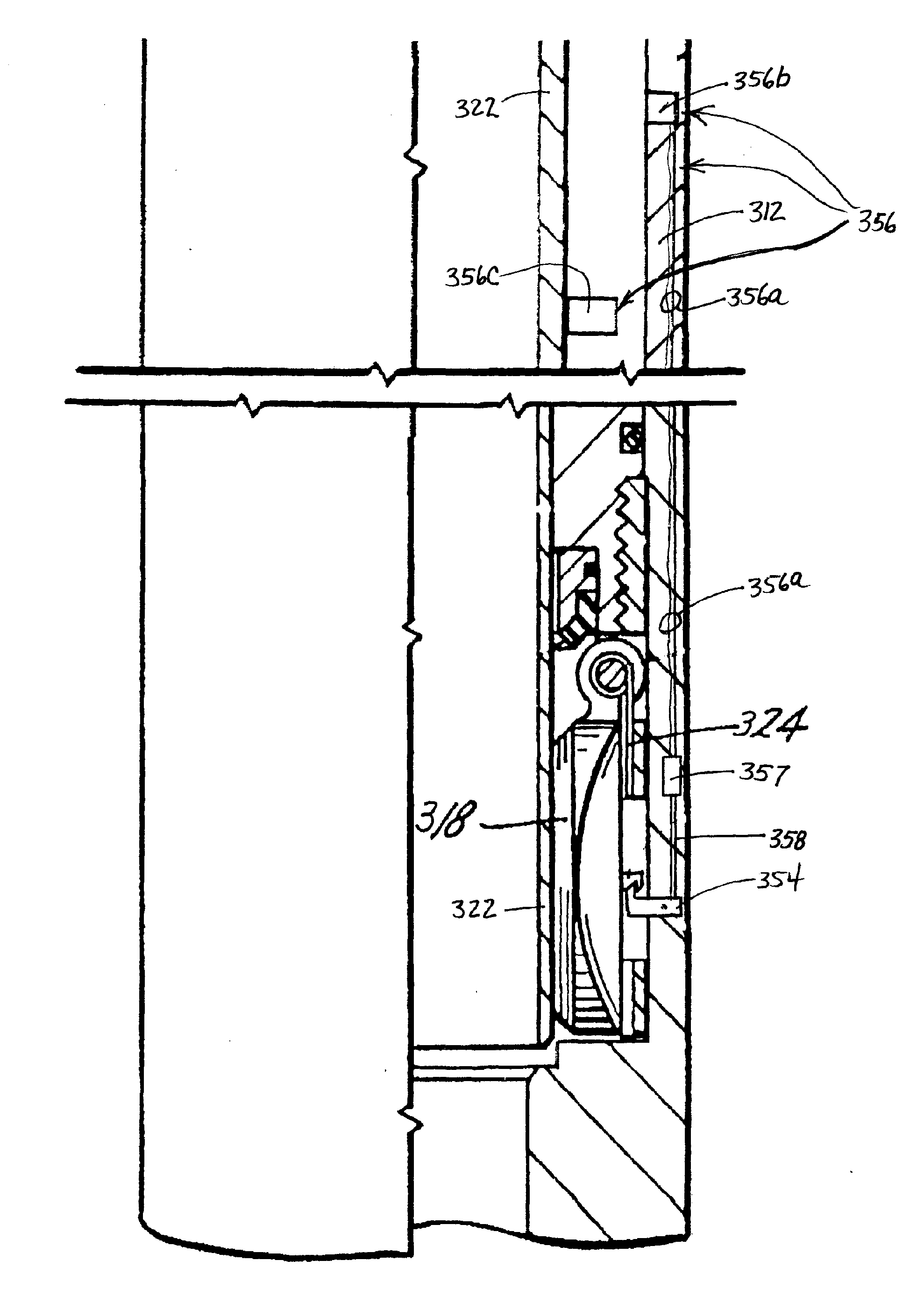
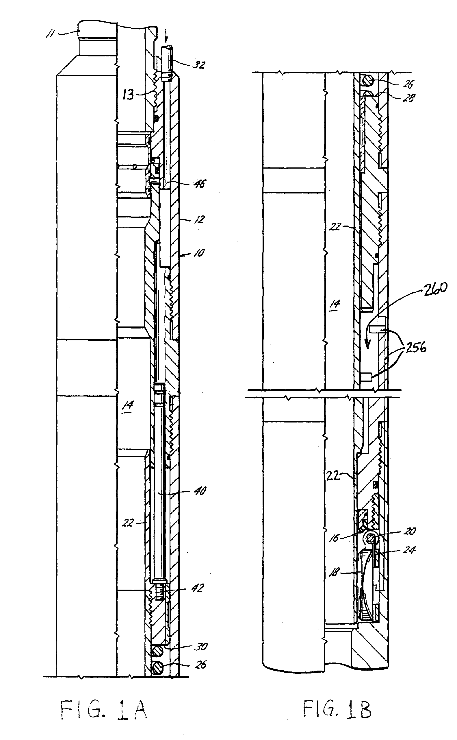
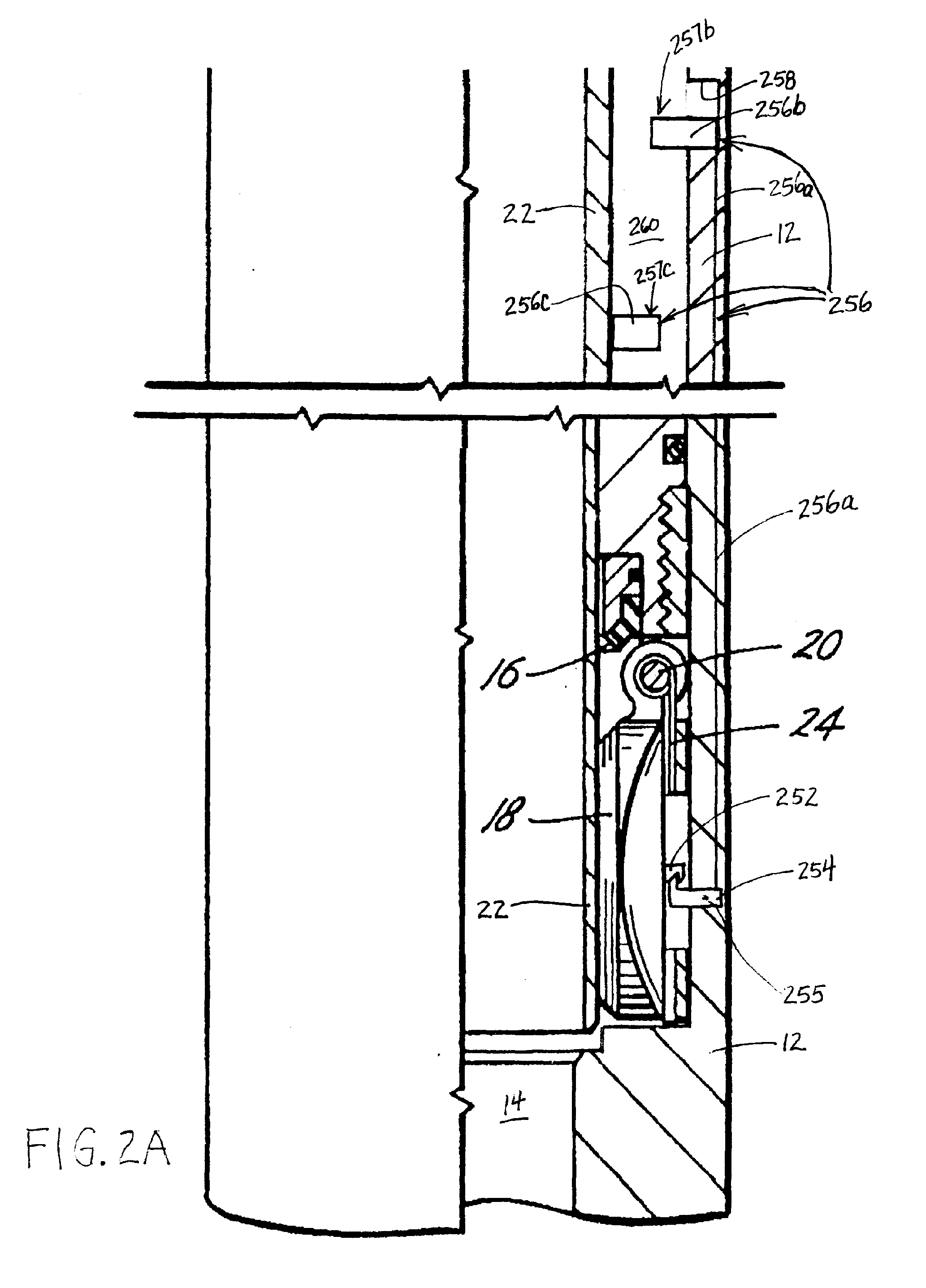
[0029] Referring now to the drawings, and in particular to FIGS. 1A-1B and 2A-2D, the subsurface safety valve of the present invention is generally indicated by the reference numeral 10 and is shown as being of a nonretrievable type for connection in a wellbore conduit or tubing string 11 such as by a threaded box 13 at one end and a threaded pin (not shown) at the other end for connecting the safety valve 10 directly into the tubing string 11 of a wellbore.

[0030] The safety valve 10 generally includes a tubular body or housing 12 adapted to be connected in the wellbore tubing string 11 to form a part thereof. The tubular body 12 defines a fluid passageway or bore 14 to permit hydrocarbon (or other downhole fluid) production therethrough under normal operating conditions. The safety valve 10 is adapted to close or be closed in response to abnormal conditions such as might occur when the well overproduces, blows wild, or in event of failure of well equipment.

[0031] For this purpose...


PUM


Abstract

A subsurface safety valve comprises a tubular body adapted for placement within a wellbore and defining a fluid passageway. A valve closure member, such as a flapper valve, is carried by the tubular body and movable through a closure path between positions opening and closing the fluid passageway. An actuator, such as a biasing spring, urges the valve closure member to its closing position. A flow tube is axially-movable within the tubular body between a first position preventing the actuator from urging the valve closure member to its closing position and a second position permitting the actuator to urge the valve closure member to its closing position. A latch assembly is provided for preventing movement of the valve closure member from its opening position to its closing position until the flow tube has been urged clear of the closure path. Aspects of the safety valve are employed by a related method and system.

Description

BACKGROUND OF THE INVENTION [0001] 1. Field of the Invention [0002] The present invention relates to subsurface safety valves for controlling fluid flow in tubing or conduit disposed in a wellbore penetrating subsurface strata. [0003] 2. Background of the Related Art [0004] A subsurface safety valve, also known simply as a safety valve, is an apparatus that is used in various wellbore types (e.g., subsea, platform, land-based) to provide a “fail-safe” mechanism for closing the wellbore to prevent the uncontrolled release of hydrocarbons or other downhole fluids. A safety valve is typically actuated in emergency situations, such as blowouts, to provide a pressure barrier (oftentimes in cooperation with blowout preventers) and safeguard local personnel, equipment, and the environment. [0005] U.S. Pat. No. 4,161,219 discloses a safety valve that employs a flapper valve that is spring-biased towards a position closing a fluid passageway in the safety valve body, and a flow tube that is ...

Claims


Application Information

Patent Timeline
IPC IPC(8): E21B34/10
CPCE21B34/066E21B34/102E21B2034/005E21B2200/05E21B34/06E21B34/12E21B34/14E21B33/064E21B34/02
Inventor MACDOUGALL, THOMAS D.MAY, DWAYNE E.
Owner SCHLUMBERGER TECH CORP
Why Eureka
Try Eureka