Seat reclining apparatus for vehicle

a technology for reclining apparatus and seats, which is applied in the direction of vehicle components, vehicle arrangements, movable seats, etc., can solve the problems of increasing the number of parts, the seat may not endure the load, and the reclining mechanism to receiv

Active Publication Date: 2007-06-21
AISIN SEIKI KK
View PDF3 Cites 17 Cited by
  • Summary
  • Abstract
  • Description
  • Claims
  • Application Information

AI Technical Summary

Benefits of technology

[0008]According to an aspect of the present invention, a seat reclining apparatus for a vehicle includes a first plate attached to one of a seat cushion and a seatback and including internal gear teeth, the first plate provided at one side in a width direction of a seat, a second plate attached to the other one of the seat cushion and the seatback and including external gear teeth engaging with the internal gear teeth of the first plate, a total number of the external gear teeth being smaller than a total number of the internal gear teeth of the first plate, the second plate provided at the one side in the width direction of the seat, a third plate attached to the one of the seat cushion and the seatback and including internal gear teeth, the third plate provided at the one side in the width direction of the seat, and a fourth plate attached to the other one of the seat cushion and the seatback and including external gear teeth engaging with the internal gear teeth of the third plate, a total number of the external gear teeth being smaller than a total number of the internal gear teeth of the third plate, the fourth plate provided at the one side in the width direction of the seat. The seat reclining apparatus for a vehicle further includes a shaft rotatably supported by the first and third plates, a first and second wedge members arranged between one of the first and second plates and the third and fourth plates and biased in a direction where an amount of eccentricity between the internal gear teeth and the external gear teeth of the one of the first and second plates and the third and fourth plates is increased so as to maintain a position at which the internal gear teeth and the external gear teeth engage with each other, a first cam provided at the shaft and pressing the wedge members to integrally rotate therewith in response to a rotation of the shaft so that the position at which the internal gear teeth and the external gear teeth engage with each other is shifted in a circumferential direction, a support member arranged between the other one of the first and second plates and the third and fourth plates and engaging with the third plate and the fourth plate when an amount of eccentricity between the internal gear teeth and the external gear teeth of the other one of the first and second plates and the third and fourth plates reaches a predetermined level, and a second cam provided at the shaft and pressing the support member to integrally rotate therewith in response to a rotation of the shaft. The amount of eccentricity defined by the support member is smaller than the amount of eccentricity defined by the wedge members.

Problems solved by technology

However, according to JP07-255553A, in the cases where the seat reclining apparatus is applied to a belt integrated seat in which a seatbelt and its peripheral structure are integrated into a seat, an absolute strength of the seat is weak against a large load added to the seatback in the event of a vehicle collision and thus the seat may not endure the load at that time.
In addition, in the event of the vehicle collision, the internal gear teeth and the external gear teeth of the other one of the reclining mechanisms make contact with each other upon deformation of the internal gear teeth and the external gear teeth of one of the reclining mechanisms, thereby causing both the reclining mechanisms to receive the load at that time.
According to the seat reclining apparatus disclosed in JP3018566B2, the shapes of the respective internal gear teeth and the external gear teeth of two reclining mechanisms are different and thus two types of parts are required for engagement of the gear teeth, which leads to an increase of the number of parts.
Accordingly, looseness is generated in the seatback, which may cause a decrease of quality feeling.

Method used


Image

  • Seat reclining apparatus for vehicle
  • Seat reclining apparatus for vehicle
  • Seat reclining apparatus for vehicle

Examples


Embodiment Construction

[0017]An embodiment of the present invention will be explained with reference to the attached drawings. The embodiment is employed in a so-called belt integrated seat mounted in a vehicle and in which a three-point seat belt and a peripheral structure thereof are integrated. According to the present embodiment, a shoulder anchor is attached on one side (i.e., an outer side or a door side, corresponding to a left side in FIG. 1A) of a seatback in a width direction of a seat 1.

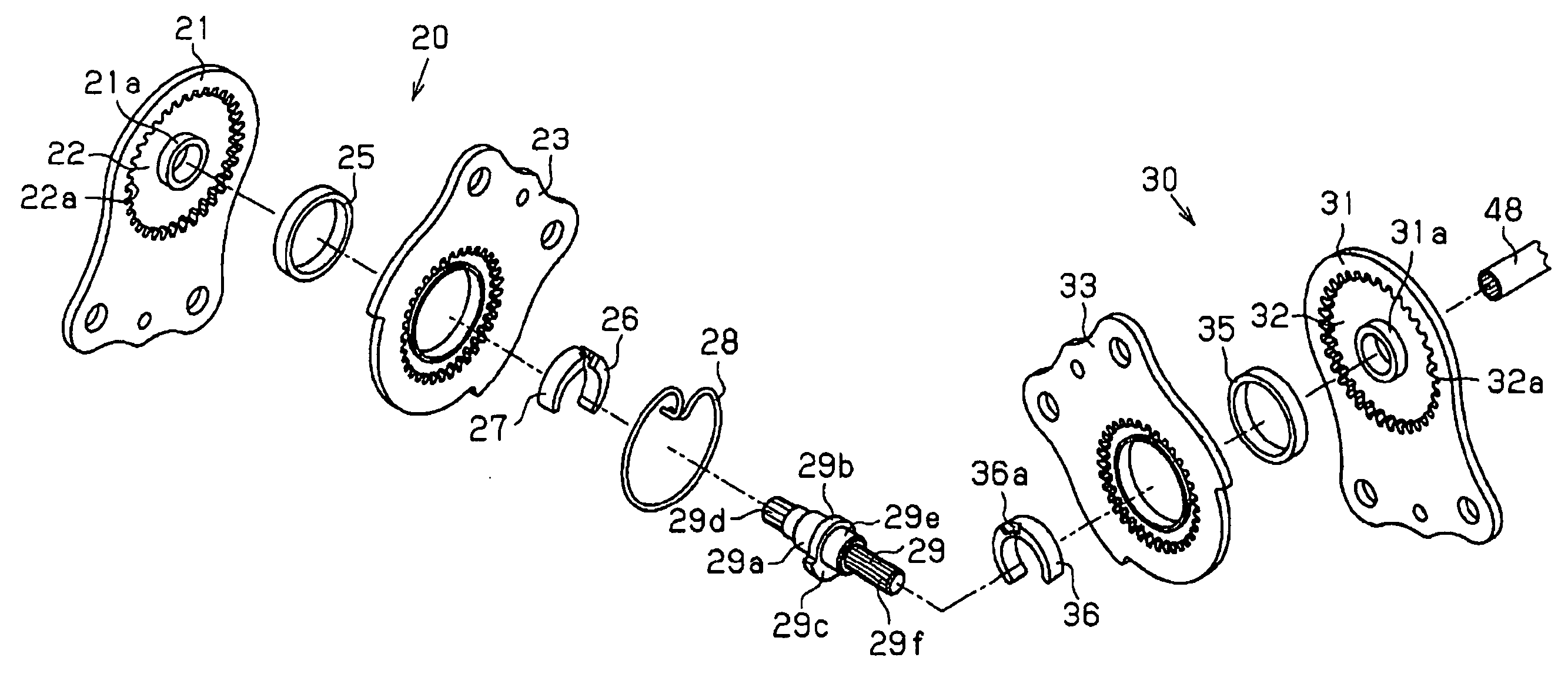
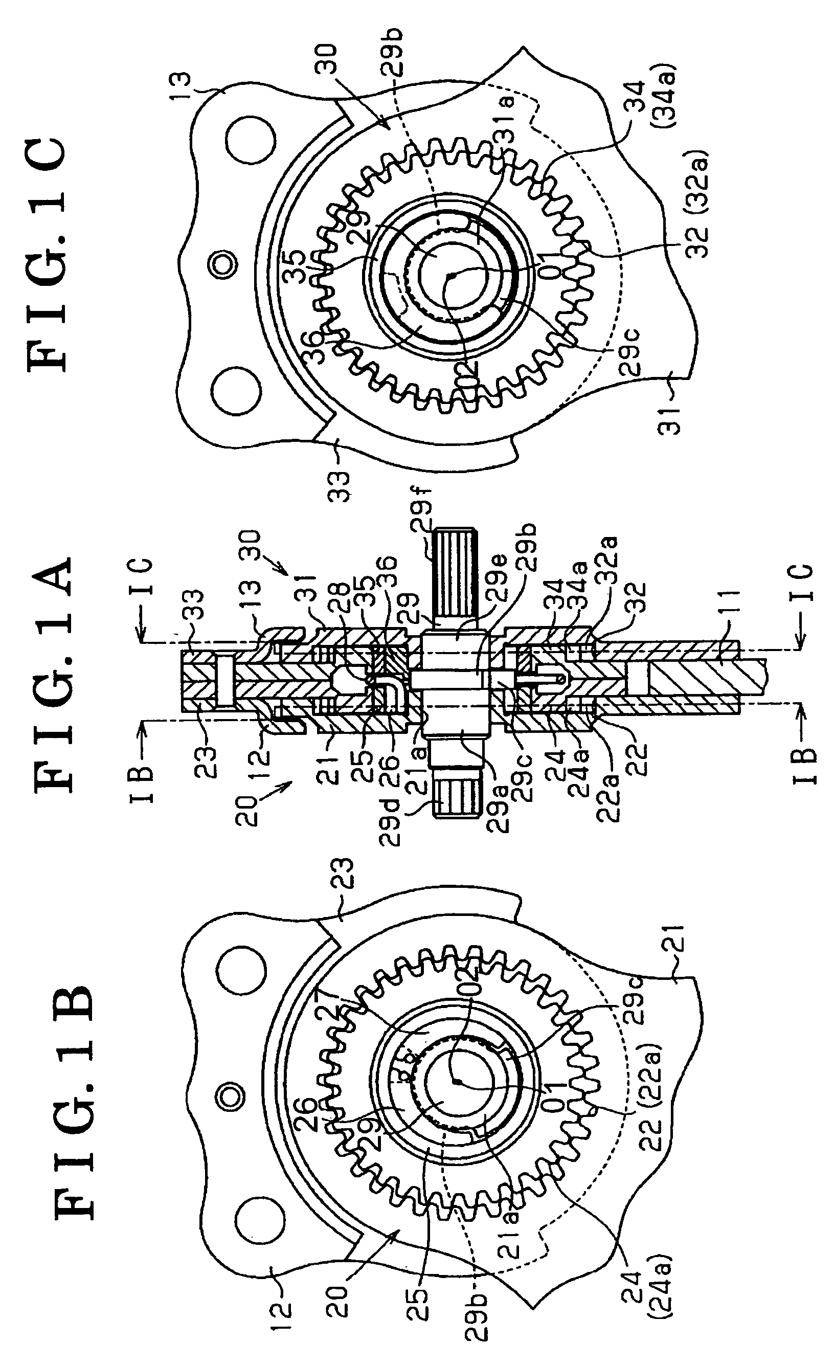
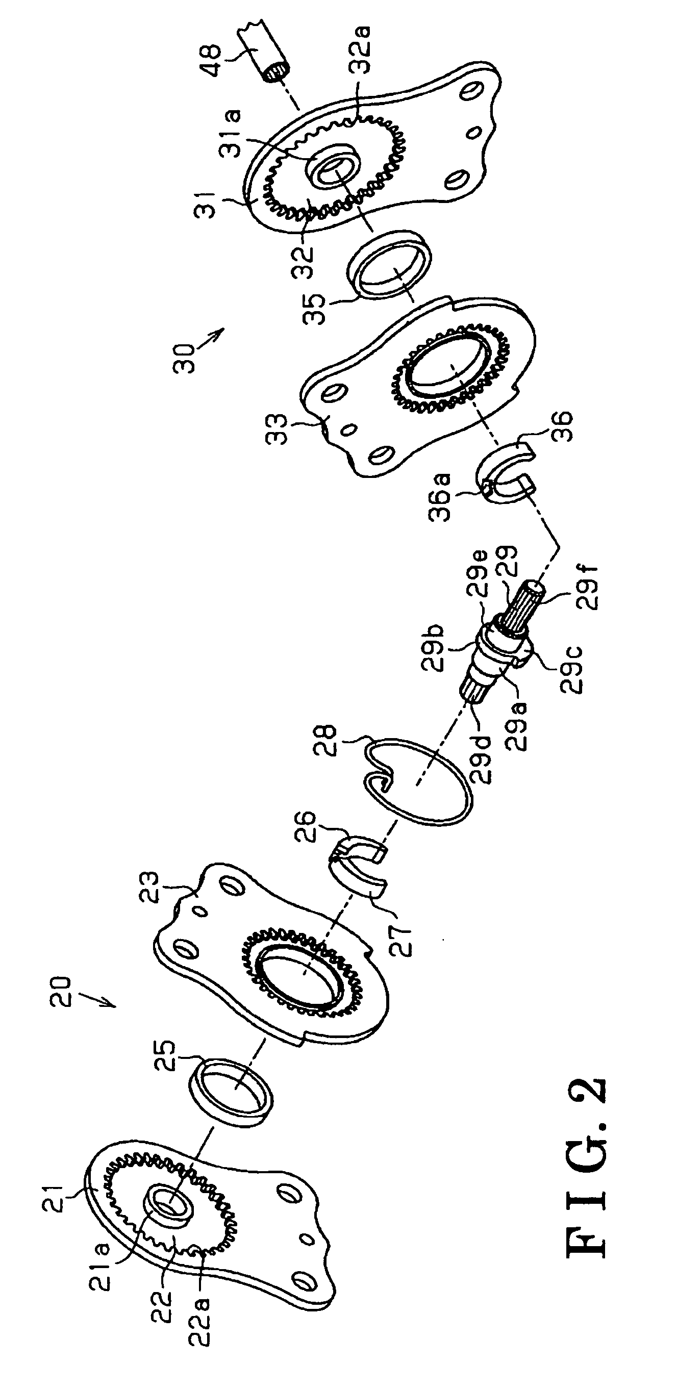
[0018]FIG. 1A is a cross-sectional view of a structure on one side of a seat reclining apparatus for a vehicle in a seat width direction. FIG. 1B is a cross-sectional view taken along the line IB-IB in FIG. 1A. FIG. 1C is a cross-sectional view taken along the line IC-IC in FIG. 1A. FIG. 2 is an exploded perspective view showing a structure of one side of the seat reclining apparatus in the seat width direction. FIG. 5 is a view of a seat 1 to which the seat reclining apparatus is mounted.

[0019]As shown in FIG. ...


PUM


Abstract

A seat reclining apparatus for a vehicle includes a first plate including internal gear teeth, a second plate including external gear teeth, a third plate including internal gear teeth, a fourth plate including external gear teeth, a shaft rotatably supported by the first and third plates, a first and second wedge members, a first cam pressing the wedge members to integrally rotate therewith, a support member arranged between the other one of the first and second plates and the third and fourth plates and engaging with the third plate and the fourth plate when an amount of eccentricity between the internal gear teeth and the external gear teeth reaches a predetermined level, and a second cam pressing the support member to integrally rotate therewith. The amount of eccentricity defined by the support member is smaller than that defined by the wedge members.

Description

CROSS REFERENCE TO RELATED APPLICATIONS[0001]This application is based on and claims priority under 35 U.S.C. § 119 to Japanese Patent Application No. 2005-363958, filed on Dec. 16, 2005, the entire content of which is incorporated herein by reference.FIELD OF THE INVENTION[0002]This invention generally relates to a seat reclining apparatus for a vehicle.BACKGROUND[0003]A known seat reclining apparatus for a vehicle intended for inclining a seatback relative to a seat cushion is disclosed in JP07-255553A. The seat reclining apparatus disclosed includes a lower plate attached to a seat cushion and having internal gear teeth, and an upper plate attached to a seatback and having external gear teeth. The external gear teeth engage with the internal gear teeth in a state where the total number of the external gear teeth is smaller than that of the internal gear teeth. An angle of inclination of the upper plate relative to the lower plate is sequentially adjustable by a circumferential mo...

Claims


Application Information

Patent Timeline
Patent Type & Authority Applications(United States)
IPC IPC(8): B60N2/02
CPCB60N2/2252B60N2/2254
Inventor ITO, SADAOYAMADA, YUKIFUMI
Owner AISIN SEIKI KK
Why Eureka
Try Eureka