Tilting-pad bearing used for rotors

A rotor and bearing technology, applied in the field of bearings, can solve the problems of easy formation of negative pressure, weakened pad stability, and increased gap between pads and rotors, preventing irregular swings, preventing oil film instability, and increasing stability. Effect

Active Publication Date: 2016-03-02
ZHONGCHE GRP TAIZHOU NO 7816 FACTORY
View PDF6 Cites 2 Cited by
  • Summary
  • Abstract
  • Description
  • Claims
  • Application Information

AI Technical Summary

Problems solved by technology

[0003] At present, due to market demand, the span of the rotor is getting longer and longer, the diameter of the rotor is getting bigger and bigger, the weight of the rotor is getting heavier, and the working speed of the unit is getting higher and higher. Correspondingly, such as the rotor installed on the steam turbine rotor The weight and shape of the tilting pad bearings also increase accordingly. During the use of the conventional tilting pad bearings used in the installation of steam turbine rotors in the prior art, as the span of the rotor becomes longer, the diameter of the rotor becomes larger, the rotor The increase in mass, the higher and higher operating speed of the unit, and the increase in the weight and size of the tilting pad bearings lead to the fact that after the tilting pad bearings are installed on the rotor, the center of the rotor deviates from the bearing due to the gravity of the rotor or the external load. center e (as in Figure 1-Figure 4 As shown), the gap between the non-loaded part of the pad and the rotor becomes larger, which in turn leads to the weakening of the oil film stiffness and oil film damping of the non-loaded part of the pad, resulting in the weakening of the stability of the pad; if the deviation e is too large, it will lead to non-loaded The state between the bearing tile surface and the journal is larger in the middle and smaller on both sides (such as figure 2 As shown), it is easy to form a negative pressure during the working process, which makes the oil film force of this part of the tile unstable during the working process, and the tile swings irregularly

Method used


Image

  • Tilting-pad bearing used for rotors
  • Tilting-pad bearing used for rotors
  • Tilting-pad bearing used for rotors

Examples


Embodiment 1

[0026] Such as Image 6 Shown: a tilting pad bearing for a rotor, including a housing 2, several load-bearing pads 3 and several non-load-bearing pads 4, the non-load-bearing pads 4 are provided with a device for connecting the rotor 1 to the corresponding The non-bearing tiles 4 maintain balance and stability and are used to adjust the first gasket 5 of the preload value of the non-bearing tiles 4; the bearing tiles 3 are provided with a balance and For a stable second gasket 6 , the thickness of the first gasket 5 is greater than that of the second gasket 6 .

[0027] When there are five radial pad bearings and the load acts on the pads, the number of bearing pads 3 is 3, and the number of non-loading pads 4 is 2;

[0028] A second gasket 6 is designed on the bearing pad 3 to maintain balance and stability between the rotor 1 and the corresponding bearing pad 3, and a first gasket 5 is designed on the non-bearing pad 4 for both It is used to keep the rotor 1 and the corres...

Embodiment 2

[0034] Such as Figure 7 Shown: This embodiment is basically the same as Embodiment 1, the only difference is that when there are five radial pad bearings and the load acts between the pads, the number of bearing pads 3 is 2, The number of non-bearing tiles 4 is 3, for the convenience of observation, the Figure 7 The load-bearing tile 3 is marked A, and the three non-bearing tiles are respectively marked B1, B2 and B1 in turn.

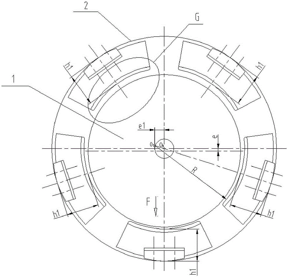
[0035] Such as Figure 7 Shown: According to the principle of force distribution, the gap between the non-load bearing pad 4 marked with B1 and the rotor 1 is smaller than the gap between the non-load bearing pad 4 marked with B2 and the rotor 1, then the gap between the non-load bearing pad 4 marked with B2 and the rotor 1 is smaller. Adding the thickness &2 of the first gasket 5 on 4 is larger than adding the thickness &1 of the first gasket 5 on the non-bearing tile 4 marked with B1, and the traditional tile eccentricity is e1 (such as figure 2 s...

Embodiment 3

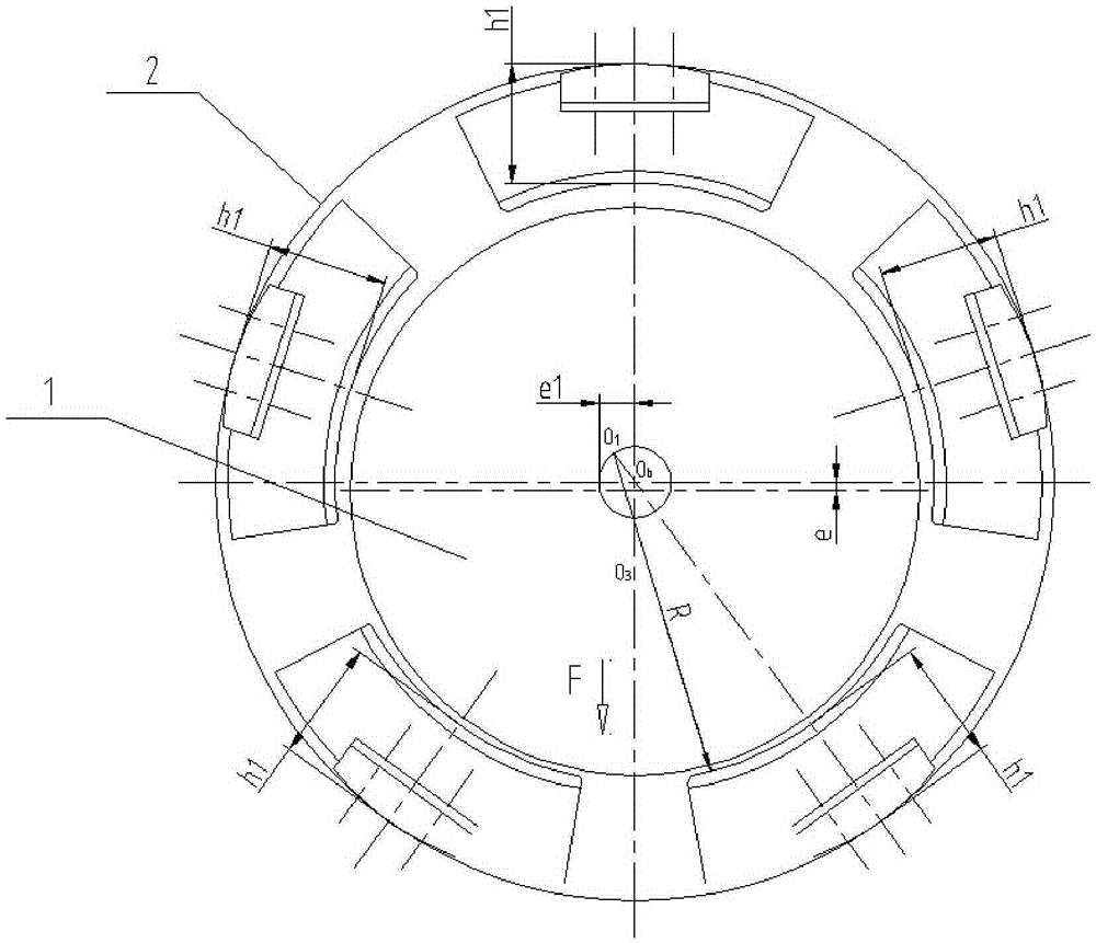
[0038] Such as Figure 8 Shown: This embodiment is basically the same as Embodiment 1, the only difference is that when there are 4 pads with radial tilting pad bearings and the load acts between the pads, the number of bearing pads 3 is 2, The number of non-bearing tiles 4 is 2, for the convenience of observation, the attached Figure 8 The bearing tiles 3 and non-bearing tiles 4 are marked accordingly, wherein the bearing tile 3 is marked with A, and the non-bearing tile 4 is marked with B.

[0039] The traditional tile eccentricity is e1 (such as Figure 4 shown), and after adding the first gasket 5 and the second gasket 6, the eccentric distance of the non-bearing pad 4 is e2=e1+&, where & is the thickness of the first gasket 5 minus the second gasket 6 Thickness values ​​(eg Image 6 As shown), after adding the first gasket 5 and the second gasket 6, the eccentricity of the non-load bearing pad 4 increases, so the oil film stiffness and oil film damping between the non...


PUM


Abstract

The invention relates to the technical field of bearings, in particular to a tilting-pad bearing used for rotors. The tilting-pad bearing comprises a shell, a plurality of bearing pads and a plurality of non-bearing pads. Second gaskets used for keeping the rotors and the corresponding bearing pads balanced and stable are arranged on the bearing pads. First gaskets used for keeping the rotors and the corresponding non-bearing pads balanced and stable and used for increasing pre-loading values of the corresponding non-bearing pads are arranged on the non-bearing pads. The thickness of the first gaskets is larger than the thickness of the second gaskets. The tilting-pad bearing is simple in structure and high in practicability.

Description

technical field [0001] The invention relates to the technical field of bearings, in particular to a tilting pad bearing for a rotor. Background technique [0002] Tilting pad support bearings are usually composed of 3 to 5 or more arc-shaped pads that can tilt freely on the fulcrum, so they are also called live multi-pad support bearings, and also called swing pad bearings. Because its pads can swing freely with the speed, load and bearing temperature, multiple oil wedges are formed around the journal. And the pressure of each oil film always points to the center, which has high stability. It can be used in turbo compressors, expanders, gearboxes, water pumps and other occasions. [0003] At present, due to market demand, the span of the rotor is getting longer and longer, the diameter of the rotor is getting bigger and bigger, the weight of the rotor is getting heavier, and the working speed of the unit is getting higher and higher. Correspondingly, such as the rotor insta...

Claims


Application Information

Patent Timeline
Patent Type & Authority Applications(China)
IPC IPC(8): F16C23/04
CPCF16C23/04
Inventor 李必相林正辉杨杰
Owner ZHONGCHE GRP TAIZHOU NO 7816 FACTORY
Why Eureka
Try Eureka