

Three-axis free bending die and guiding mechanism matching optimization design method
A guiding mechanism and optimized design technology, applied in computing, metal processing equipment, forming tools, etc., can solve the problems of geometric limitations in displacement distance and deflection angle, affecting motion stability, complex assembly structure, etc., and achieve important engineering application value , Increase motion stability, obvious economic benefits
- Summary
- Abstract
- Description
- Claims
- Application Information
AI Technical Summary
Problems solved by technology
Method used
Image

Examples
Embodiment 1
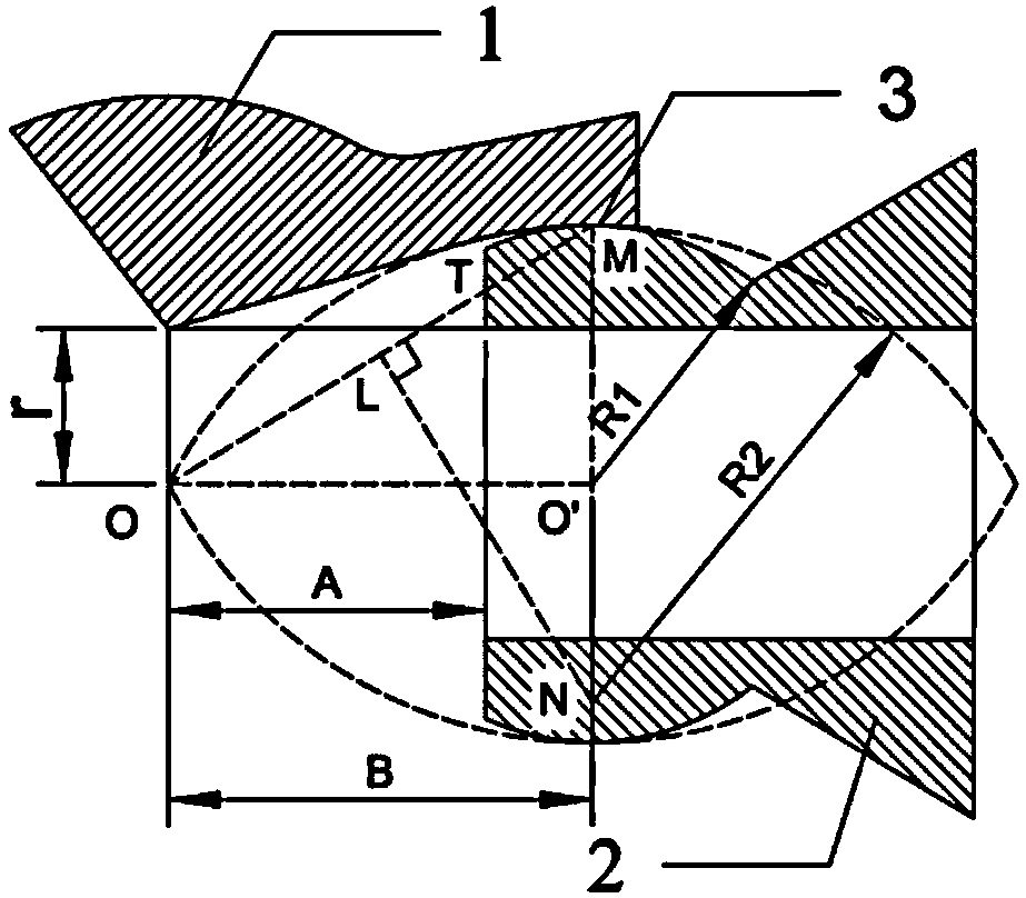
[0040] The outer diameter of the tube blank is D, the target minimum bending radius is 2.5D, and the limit eccentricity of the bending die is 0.7D. In order to determine all the dimensions of the mold, some dimensions that can be calculated from the above basic forming requirement parameters are calculated in advance, and some dimensions that cannot be directly calculated are determined according to empirical values. Therefore, the order of determining the mold size is: (1) Determine the distance A value between the center of the bending die and the front end of the guiding mechanism: (2) Determine some dimensions that cannot be directly calculated according to empirical values: B=2D, R0=1.8D, R1=1.2D, C=0.8D, α=60°; (3) Determine the matching of the bending die and the guide mechanism The spherical radius of the spherical envelope surface: R2 = (B 2 +R1 2 ) / 2R1=2.27D; (4) determine the length of the spherical envelope surface at the end of the bending die: (5) Check the ...
Embodiment 2
[0042] The outer diameter of the tube blank is D, the target minimum bending radius is 3.0D, and the limit eccentricity of the bending die is 0.7D. In order to determine all the dimensions of the mold, some dimensions that can be calculated from the above basic forming requirement parameters are calculated in advance, and some dimensions that cannot be directly calculated are determined according to empirical values. Therefore, the order of determining the mold size is: (1) Determine the distance A value between the center of the bending die and the front end of the guiding mechanism: (2) Determine some dimensions that cannot be directly calculated according to empirical values: B=2.5D, R0=2.0D, R1=1.6D, C=1.0D, α=60°; (3) Make sure that the bending die matches the guide mechanism The spherical radius of the spherical envelope surface: R2 = (B 2 +R1 2 ) / 2R1=2.75D; (4) determine the length of the spherical envelope surface at the end of the bending die: (5) Check the four ...
Embodiment 3
[0044] The outer diameter of the tube blank is D, the target minimum bending radius is 3.5D, and the limit eccentricity of the bending die is 0.7D. In order to determine all the dimensions of the mold, some dimensions that can be calculated from the above basic forming requirement parameters are calculated in advance, and some dimensions that cannot be directly calculated are determined according to empirical values. Therefore, the order of determining the mold size is: (1) Determine the distance A value between the center of the bending die and the front end of the guiding mechanism: (2) Determine some dimensions that cannot be directly calculated according to empirical values: B=2.8D, R0=2.2D, R1=1.8D, C=1.2D, α=60°; (3) Make sure that the bending die matches the guide mechanism The spherical radius of the spherical envelope surface: R2 = (B 2 +R1 2 ) / 2R1=3.07D; (4) determine the length of the spherical envelope surface at the end of the bending die: (5) Check the four ...
PUM
 Abstract
Description
Claims
Application Information