
System, apparatus and method for supplying electric power, apparatus and method for receiving electric power, storage medium and program

a technology for electric power supply and electric power supply, which is applied in the direction of program control, safety/protection circuit, instruments, etc., can solve the problem of taking a long time to fully charge the battery

Active Publication Date: 2007-06-21
SONY CORP
View PDF5 Cites 413 Cited by
  • Summary
  • Abstract
  • Description
  • Claims
  • Application Information

AI Technical Summary

Benefits of technology

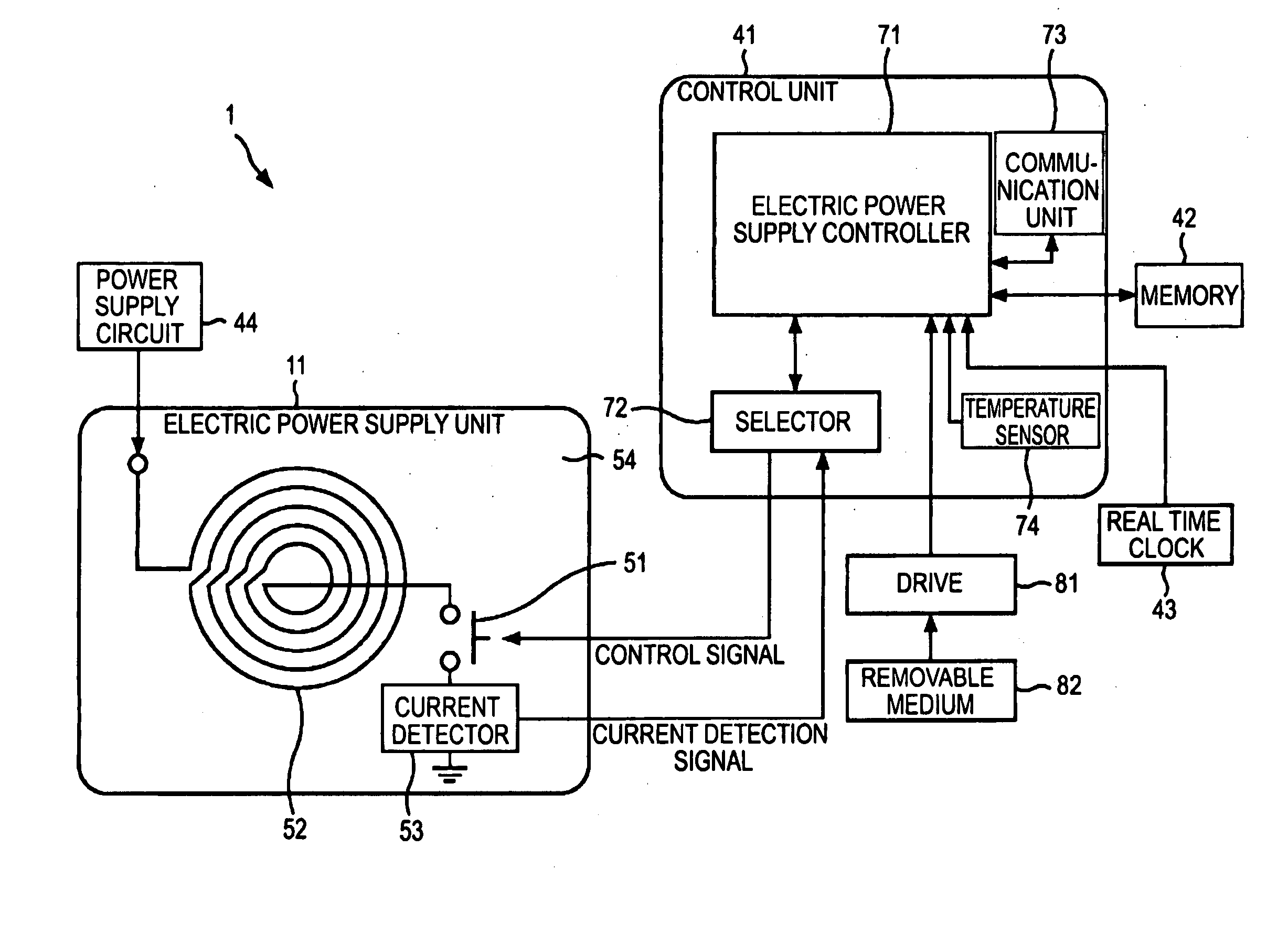
The patent text describes an electric power supply system that allows for quick charging of a battery by supplying electric power to an electric power reception apparatus through multiple electric power supply means. The system includes an electric power supply apparatus with multiple electric power supply means and a selection means for selecting the most suitable electric power supply means for the electric power reception apparatus. The electric power reception apparatus includes an electric power reception means for receiving electric power and a transmitting unit for wirelessly transmitting control information to the electric power supply apparatus. The system can authenticate the electric power reception apparatus and detect overcurrent through the selected electric power supply means. The technical effect of this patent is to provide a more efficient and effective electric power supply system that allows for quick charging of batteries.

Problems solved by technology

In the known electric power supply system, electric power is supplied from a particular one of power supply coils of the electric power supply apparatus to the electric power reception coil of the electric power reception apparatus, and thus it takes a long time to completely charge the battery.

Method used


Image

  • System, apparatus and method for supplying electric power, apparatus and method for receiving electric power, storage medium and program
  • System, apparatus and method for supplying electric power, apparatus and method for receiving electric power, storage medium and program
  • System, apparatus and method for supplying electric power, apparatus and method for receiving electric power, storage medium and program

Examples


Embodiment Construction

[0036] Before embodiments of the present invention are described, correspondence between specific examples of parts / steps in the embodiments and those in the respective claims is described. This description is intended to assure those embodiments supporting the claimed invention are described in this specification. Thus, even if an element in the following embodiments is not described as relating to a certain feature of the present invention, that does not necessarily mean that the element does not relate to that feature of the claims. Conversely, even if an element is described herein as relating to a certain feature of the claims, that does not necessarily mean that the element does not relate to other features of the claims.

[0037] Furthermore, this description should not be construed as restricting that all the aspects of the invention disclosed in the embodiments are described in the claims. That is, the description does not deny the existence of aspects of the present inventio...


PUM


Abstract

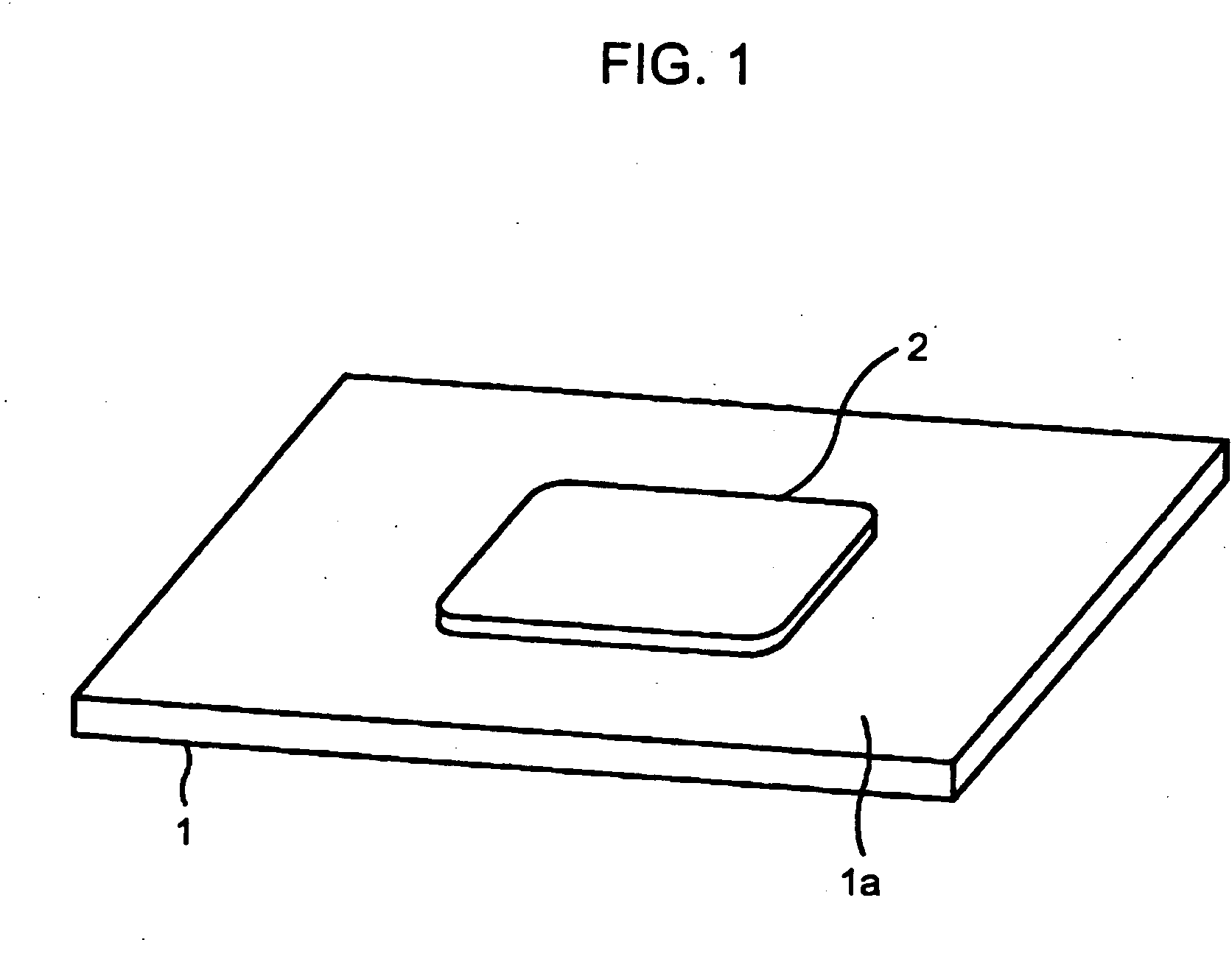
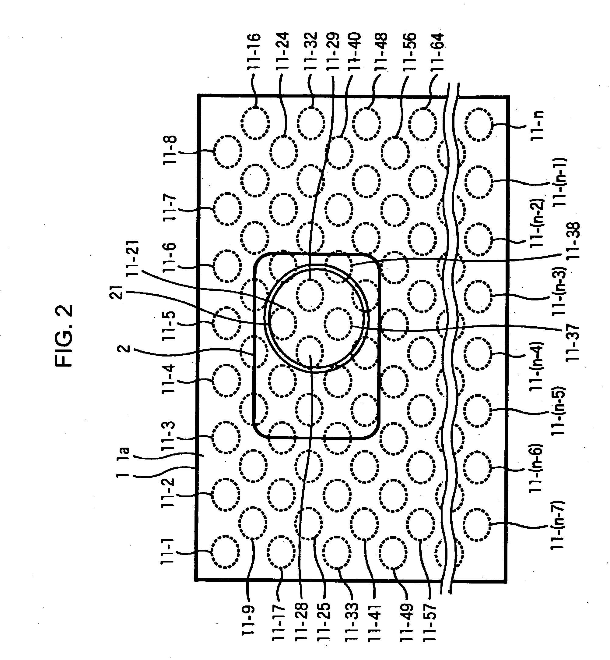
An electric power supply system includes an electric power reception apparatus and an electric power supply apparatus adapted to supply electric power to the electric power reception apparatus when the electric power reception apparatus is placed on the electric power supply apparatus. The electric power supply apparatus includes a plurality of electric power supply units adapted to supply electric power by electromagnetic induction to the electric power reception apparatus. A selection unit of the electric power supply apparatus selects, from the total plurality of electric power supply units, a plurality of electric power supply units whose location corresponds to a position where the electric power reception apparatus is placed, and a control unit controls the supply of electric power such that electric power is supplied to the electric power reception apparatus from the selected plurality of electric power supply units.

Description

CROSS REFERENCES TO RELATED APPLICATIONS [0001] The present invention contains subject matter related to Japanese Patent Application JP 2005-059747 filed in the Japanese Patent Office on Mar. 3, 2005, the entire contents of which are incorporated herein by reference. BACKGROUND OF THE INVENTION [0002] 1. Field of the Invention [0003] The present invention relates to a system, apparatus and method for supplying electric power, an apparatus and a method for receiving electric power, a storage medium and a program, and more particularly to a system, apparatus and method for supplying electric power, an apparatus and a method for receiving electric power, a storage medium and a program, that allow it to supply electric power to an electric power reception apparatus in an easy and efficient manner. [0004] 2. Description of the Related Art [0005] In many electronic devices such as a PDA (Personal Digital Assistance) device or a digital portable telephone, a battery is charged such by supp...

Claims


Application Information

Patent Timeline
Patent Type & Authority Applications(United States)
IPC IPC(8): H02J7/00
CPCH02J5/005H02J7/025H02J7/00045H02J7/00304H02J50/402H02J50/90H02J50/10H02J50/80
Inventor KOZUMA, YOSUKENISHIKAWA, SHINPEIKIMURA, SHINJIHORI, YUSUKEMIKANO, GOROIWASAKI, YUUKIONITSUKA, SHIGETOSHI
Owner SONY CORP
Learn More