High voltage pulsed power supply using solid state switches with voltage cell isolation

a technology of solid state switches and power supplies, applied in pulse generators, pulse techniques, instruments, etc., can solve the problems of stray capacitance, section may experience higher voltage, and the number of sections that can be stacked together effectively limited, so as to achieve cell isolation

Active Publication Date: 2007-06-21
STANGENES IND INC
View PDF19 Cites 26 Cited by
  • Summary
  • Abstract
  • Description
  • Claims
  • Application Information

AI Technical Summary

Benefits of technology

This patent describes two technical features for a pulse generator: 1. A ringing circuit with capacitors that provides smoother droop correction compared to traditional methods. This allows for more accurate control over the timing and duration of pulses generated by the pulse generator. 2. Isolated protective circuits within each voltage cell prevent failure from affecting other parts of the system. These circuits use diodes to allow for safe removal of malfunctioning cells while still maintaining overall functionality of the device.

Problems solved by technology

This patent discusses the technical problem of generating high-voltage pulses using traditional methods like Marx Generators. These methods require large and heavy equipment, which makes them unreliable and costly. Additionally, there is a limitation on the number of sections that can be added due to stray capacitance, which causes uneven distribution of voltage among the sections. There is a need for more efficient and reliable ways to produce these high-voltage pulses without being restricted by stray capacitance.

Method used


Image

  • High voltage pulsed power supply using solid state switches with voltage cell isolation
  • High voltage pulsed power supply using solid state switches with voltage cell isolation
  • High voltage pulsed power supply using solid state switches with voltage cell isolation

Examples


Embodiment Construction

[0030] The present invention relates to systems and methods for generating a voltage pulse. Embodiments of the invention can control an amplitude of the voltage pulse, a duration or width of the voltage pulse, a rise time of the voltage pulse, a fall time of the voltage pulse, and the like or any combination thereof Some embodiments of the invention can generate and deliver a voltage pulse without the use of transformers.

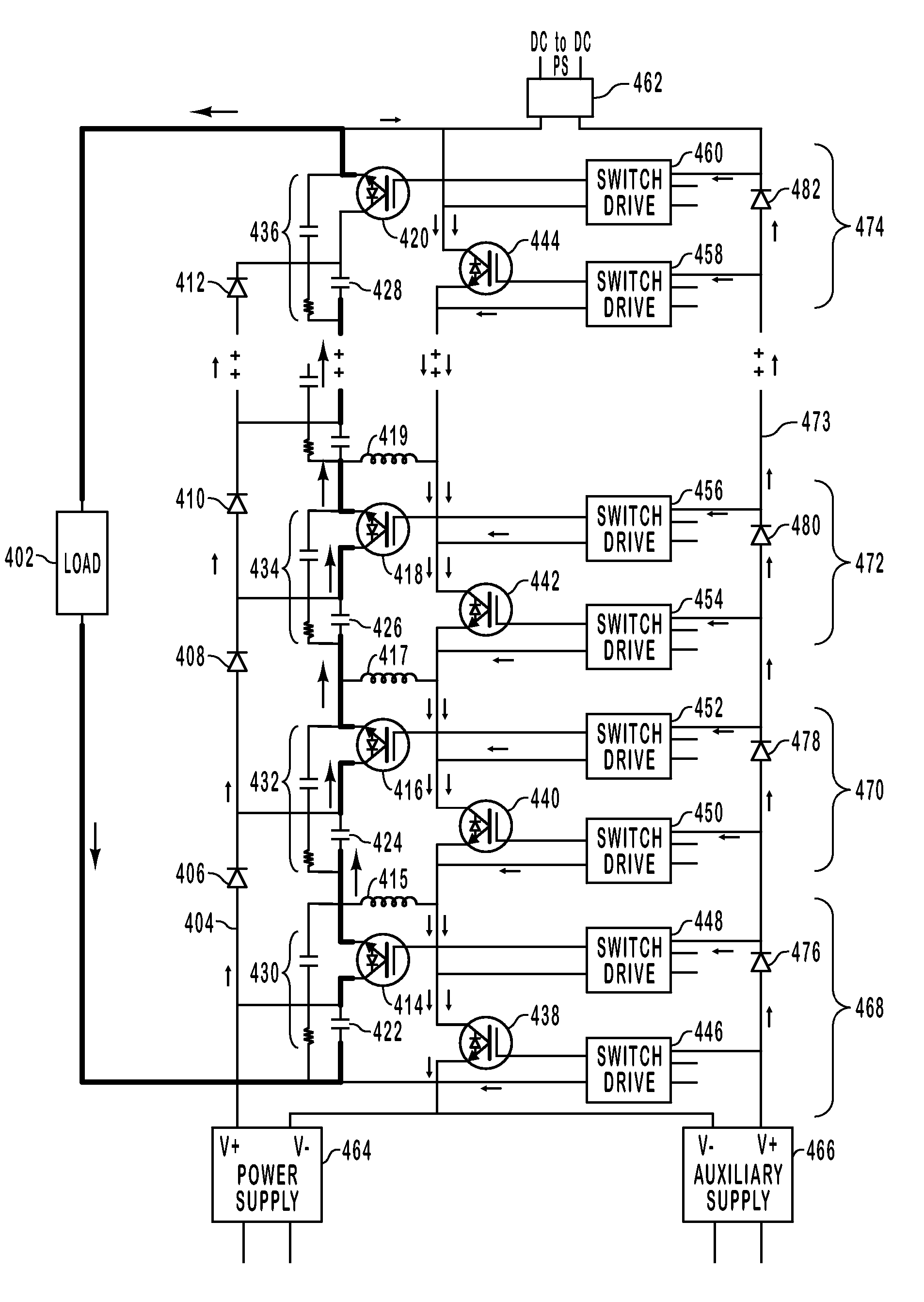
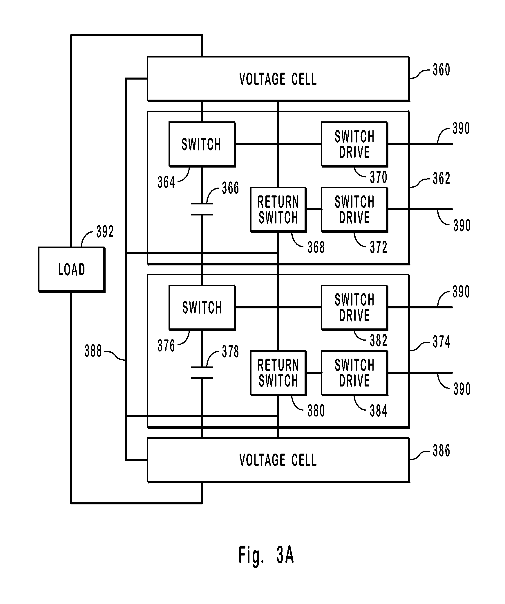
[0031] Embodiments of the invention include voltage cells that typically have both a capacitor and a switch in series. The first and last voltage cells in a series of voltage cells may be adapted to connect to the load. Return switches are also included in most voltage cells. The return switches provide a path for the charging current supplied through a diode chain or a diode chain supply line. Advantageously, the return switches eliminate the use of inductors, resistors, and isolated supplies prevalent in conventional pulse generators. The switch drives may also p...


PUM


Abstract

Systems and methods for generating a high voltage pulse. A series of voltage cells are connected such that charging capacitors can be charged in parallel and discharged in series. Each cell includes a main switch and a return switch. When the main switches are turned on, the capacitors in the cells are in series and discharge. When the main switches are turned off and the return switches are turned on, the capacitors charge in parallel. One or more of the cells can be inactive without preventing a pulse from being generated. The amplitude, duration, rise time, and fall time can be controlled with the voltage cells. Each voltage cell may also include a balance network to match the stray capacitance seen by each voltage cell. Droop compensation is also enabled. Isolation diodes ensure that a discharge current can bypass inoperable voltage cells.

Description


Claims


Application Information

Patent Timeline
Owner STANGENES IND INC
Why Eureka
Try Eureka