Magnetic head for perpendicular magnetic recording, head gimbal assembly, head arm assembly and magnetic disc drive

Active Publication Date: 2007-06-21
TDK CORPARATION
View PDF9 Cites 13 Cited by
  • Summary
  • Abstract
  • Description
  • Claims
  • Application Information

AI Technical Summary

Benefits of technology

[0019]It is an object of the invention to provide a magnetic head for perpendicular magnetic recording that is capable of suppressing an occurrence of pole erase without makin

Problems solved by technology

However, if the track width is reduced, write characteristics such as an overwrite property that is a parameter indicating an overwriting capability are degraded.
A problem that the structure of the pole layer is complicated is found in each of the techniques disclosed in JP-A 2005-38535, JP-A 2005-174449, JP-A 2004-281023, and U.S. Pat. No. 6,628,478 B2.
As a result, these techniques have problems of an increase in costs for manufacturing the magnetic head and a reduction in throughput.
According to the techniques disclosed

Method used


Image

  • Magnetic head for perpendicular magnetic recording, head gimbal assembly, head arm assembly and magnetic disc drive
  • Magnetic head for perpendicular magnetic recording, head gimbal assembly, head arm assembly and magnetic disc drive
  • Magnetic head for perpendicular magnetic recording, head gimbal assembly, head arm assembly and magnetic disc drive

Examples


Embodiment Construction

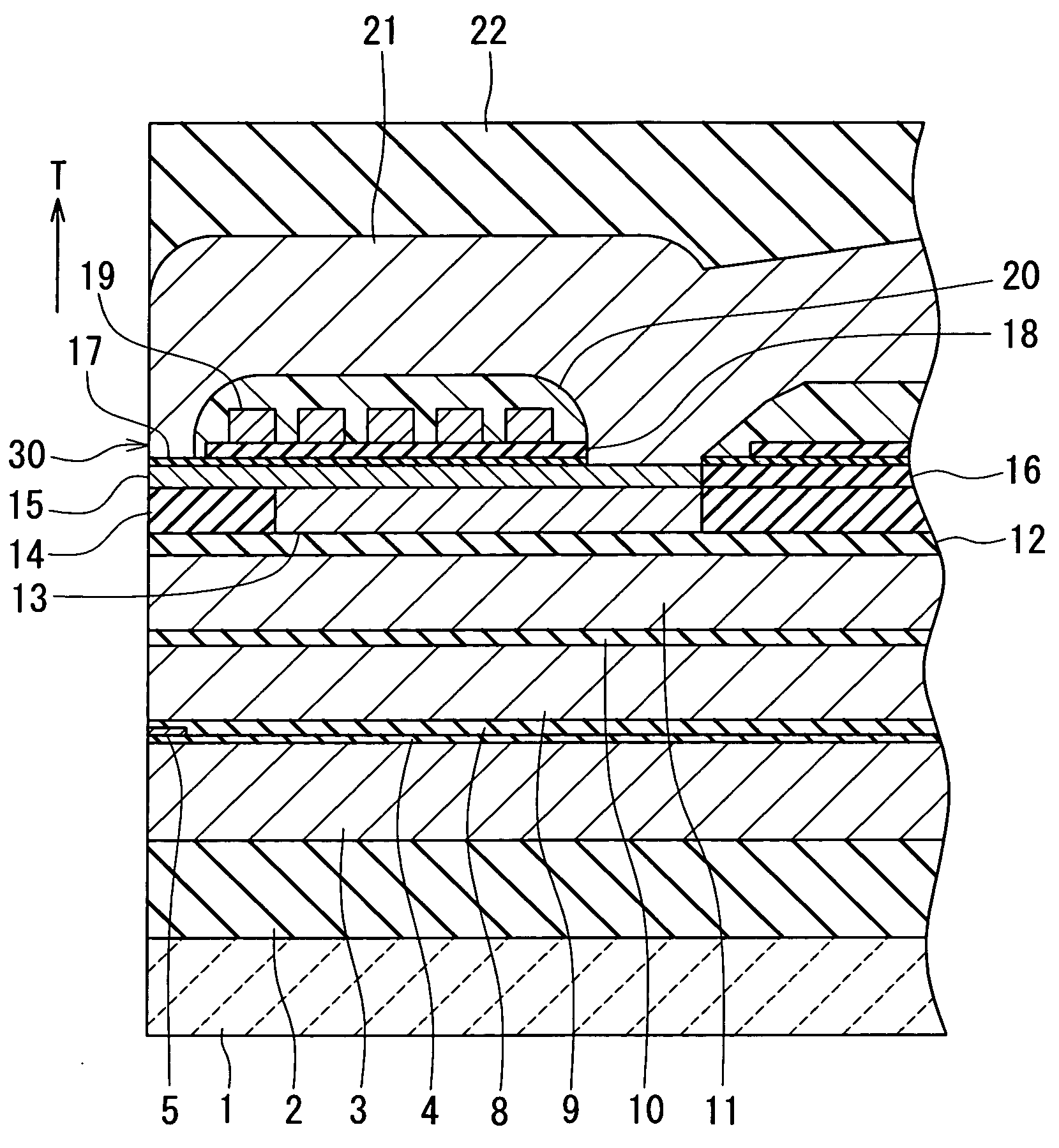
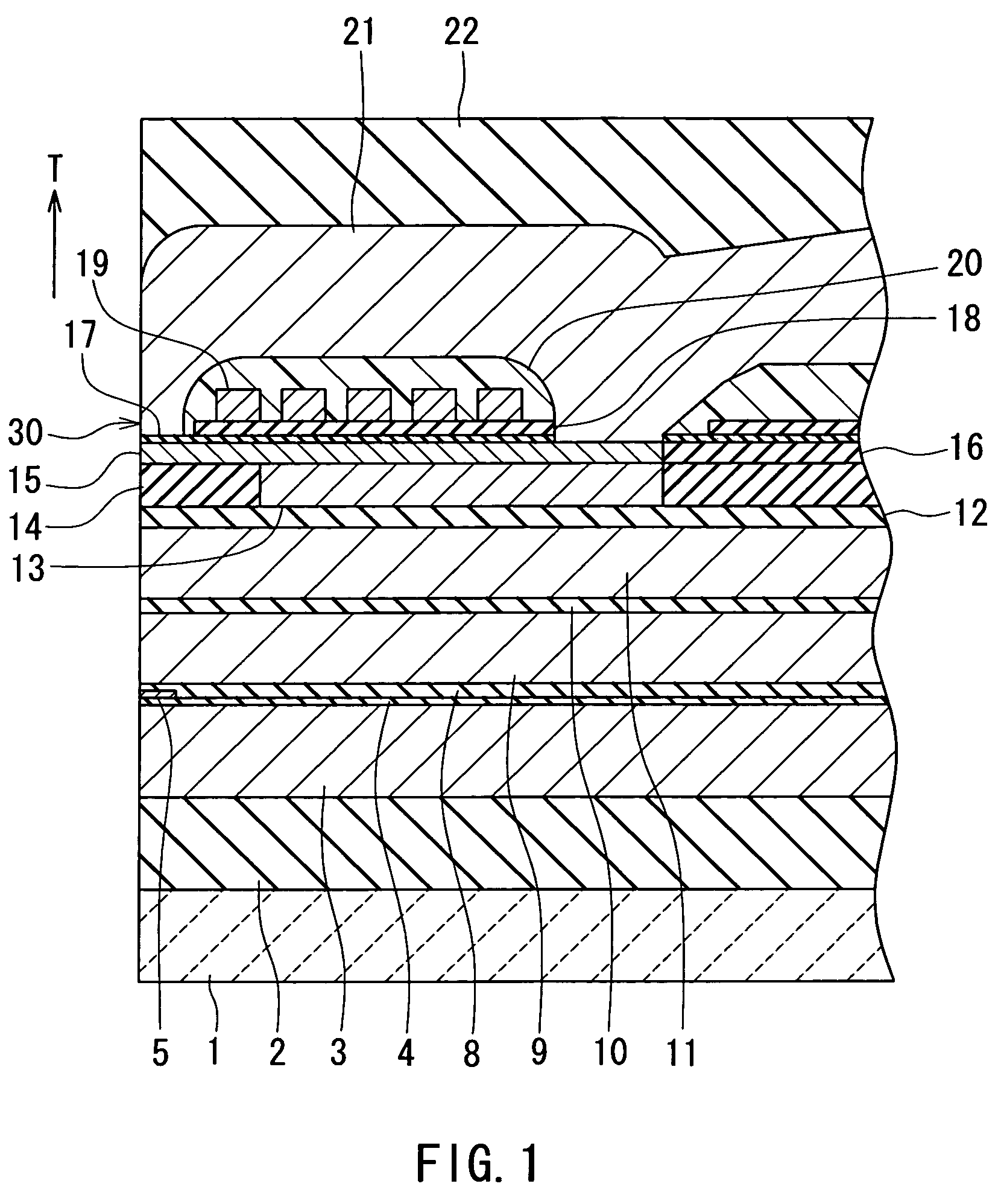
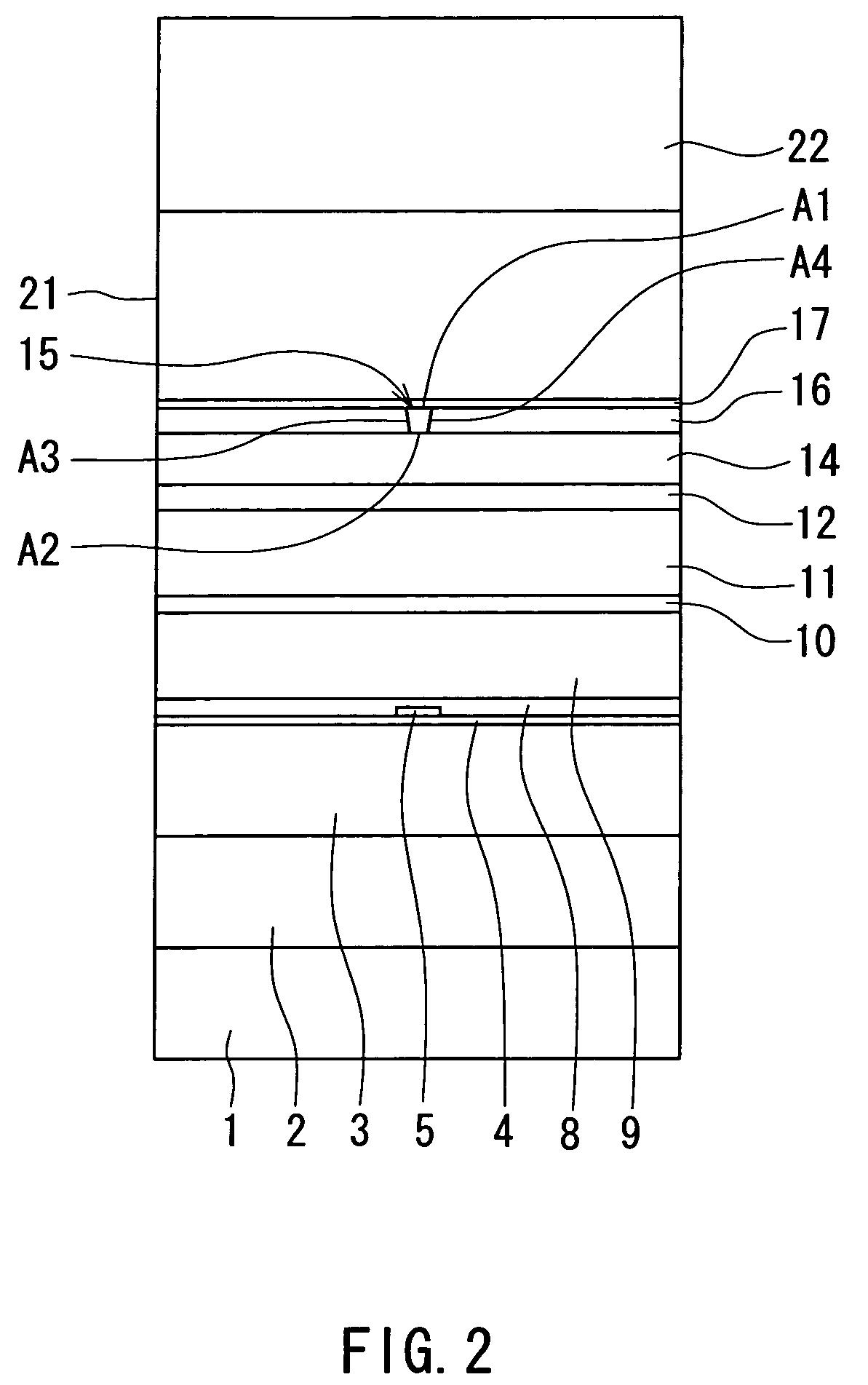
[0047]A preferred embodiment of the invention will now be described in detail with reference to the accompanying drawings. Reference is now made to FIG. 1 and FIG. 2 to describe the configuration of a magnetic head for perpendicular magnetic recording of the embodiment of the invention. FIG. 1 is a cross-sectional view illustrating the configuration of the magnetic head of the embodiment. FIG. 2 is a front view illustrating a medium facing surface of the magnetic head of the embodiment. FIG. 1 illustrates a cross section orthogonal to the medium facing surface and a surface of a substrate. The arrow indicated with T in FIG. 1 shows the direction of travel of a recording medium.

[0048]As shown in FIG. 1 and FIG. 2, the magnetic head for perpendicular magnetic recording (hereinafter simply called the magnetic head) of the embodiment comprises: a substrate 1 made of a ceramic such as aluminum oxide and titanium carbide (Al2O3—TiC); an insulating layer 2 made of an insulating material su...


PUM


Abstract

A magnetic head comprises: a medium facing surface; a coil for generating a magnetic field corresponding to data to be written on a recording medium; and a pole layer allowing a magnetic flux corresponding to the field generated by the coil to pass therethrough, and generating a write magnetic field for writing the data on the recording medium by means of a perpendicular magnetic recording system. The pole layer incorporates a track width defining portion and a wide portion. The track width defining portion has an end face that is located in the medium facing surface and that defines the track width. The maximum width of the wide portion is greater than the track width and equal to or greater than the length of the wide portion taken in the direction orthogonal to the medium facing surface. When the coil is generating no magnetic field, in the end face of the track width defining portion, there exist first and second regions in which the directions of components of magnetization orthogonal to the medium facing surface are opposite.

Description

BACKGROUND OF THE INVENTION[0001]1. Field of the Invention[0002]The present invention relates to a magnetic head for perpendicular magnetic recording used for recording data on a recording medium by means of a perpendicular magnetic recording system, and to a head gimbal assembly, a head arm assembly, and a magnetic disk drive each of which incorporates the magnetic head for perpendicular magnetic recording.[0003]2. Description of the Related Art[0004]The recording systems of magnetic read / write devices include a longitudinal magnetic recording system wherein signals are magnetized in the direction along the surface of the recording medium (the longitudinal direction) and a perpendicular magnetic recording system wherein signals are magnetized in the direction orthogonal to the surface of the recording medium. It is known that the perpendicular magnetic recording system is harder to be affected by thermal fluctuation of the recording medium and capable of implementing higher linear ...

Claims


Application Information

Patent Timeline
IPC IPC(8): G11B5/147
CPCG11B5/1278G11B5/3116
Inventor HIRATA, KEINOGUCHI, KIYOSHI
Owner TDK CORPARATION
Why Eureka
Try Eureka