Circuit board arrangement including heat dissipater

a technology of circuit board and heat dissipation device, which is applied in the direction of electrical apparatus contruction details, lighting and heating apparatus, and modifications by conduction heat transfer, etc., can solve the problem that the airflow provided by the fan may not provide sufficient cooling for the memory modules

Inactive Publication Date: 2007-06-21
POLARIS INNOVATIONS
View PDF21 Cites 64 Cited by
  • Summary
  • Abstract
  • Description
  • Claims
  • Application Information

AI Technical Summary

Problems solved by technology

Therefore, the airflow provided by the fan may not provide suffici...

Method used


Image

  • Circuit board arrangement including heat dissipater
  • Circuit board arrangement including heat dissipater
  • Circuit board arrangement including heat dissipater

Examples


Embodiment Construction

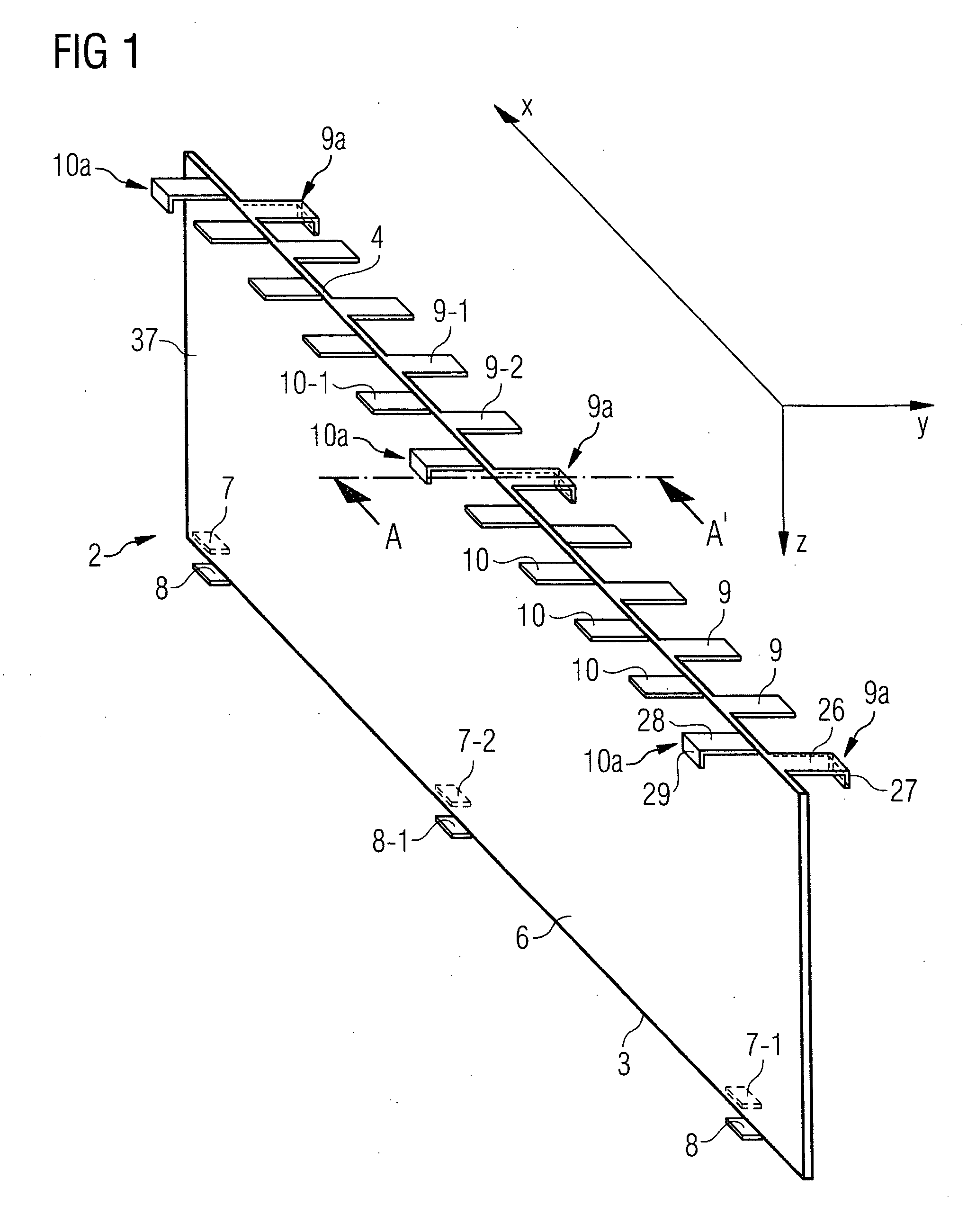
[0017]FIG. 1 depicts a perspective view of a cooling body 2 for the implementation in a circuit board arrangement 1 (not shown in FIG. 1) according to one embodiment of the present invention. The cooling body 2 may comprise a material that has a large thermal conductivity. Preferably, the material is a metal, for example copper or aluminum. The cooling body 2 includes a sheet-shaped portion 37 that extends along a plane spanned by the X direction and the Z direction as depicted in the coordinate system.

[0018] The cooling body 2 has a first edge 3 and a second edge 4 and a first surface 5 (not shown in FIG. 1) and a second surface 6. The first edge 3 and the second edge 4 extend along the first direction X.

[0019] First fixing elements 7 are disposed at the first edge 3 of the cooling body 2 and extend from the first edge 3 of the cooling body 2 along a second direction Y, that is different from the first direction X.

[0020] Second fixing elements 8 are disposed at the first edge 3 ...


PUM


Abstract

A circuit board arrangement includes a heat dissipater. A cooling body is arranged near a first circuit board and a second circuit board. Both circuit boards have electronic devices on two major surfaces. The cooling body is arranged between the electronic devices on one surface of the first circuit board and the electronic devices on one surface of the second circuit board. The circuit boards are supported by fixing elements of the cooling body.

Description

TECHNICAL FIELD [0001] The present invention relates to a circuit board arrangement and in particular to a circuit board arrangement with a heat dissipation means for the reduction of the temperature of electronic devices of the circuit board arrangement. BACKGROUND [0002] Computers typically have means for cooling some components like the central processing unit (CPU) to avoid damage to the components or to adjacent devices by excessive heat generated by those components. The means for cooling may include a fan that is installed inside the housing of the computer. The fan effects a defined airflow to provide cooling of the components. [0003] Such computers usually have a memory associated with the CPU, particularly a dynamic random access memory (DRAM). The memory comprises a multiplicity of electronic devices disposed on a circuit board. The circuit board including the multiplicity of electronic devices is commonly referred to as memory module. [0004] The memory module has a numbe...

Claims


Application Information

Patent Timeline
IPC IPC(8): H05K7/20
CPCH01L23/3672H05K1/0203H05K1/117H05K1/144H05K7/20509H01L2924/0002H05K2201/1056H01L2924/00
Inventor RAGHURAM, SIVA
Owner POLARIS INNOVATIONS
Why Eureka
Try Eureka