Lighting methods and systems

a technology of lighting and systems, applied in the field of lighting methods and systems, can solve problems such as inconvenience for large-scale installations

Active Publication Date: 2007-06-28
SIGNIFY NORTH AMERICA CORP
View PDF99 Cites 484 Cited by
  • Summary
  • Abstract
  • Description
  • Claims
  • Application Information

AI Technical Summary

Problems solved by technology

For example, many LED lighting fixtures require a separate power supply for each fixture...

Method used


Image

  • Lighting methods and systems
  • Lighting methods and systems
  • Lighting methods and systems

Examples


Embodiment Construction

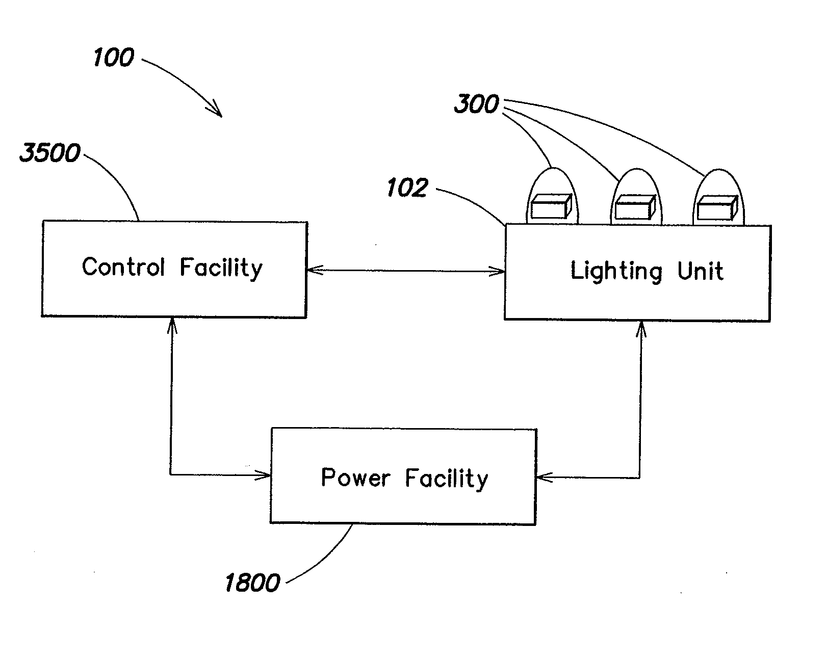
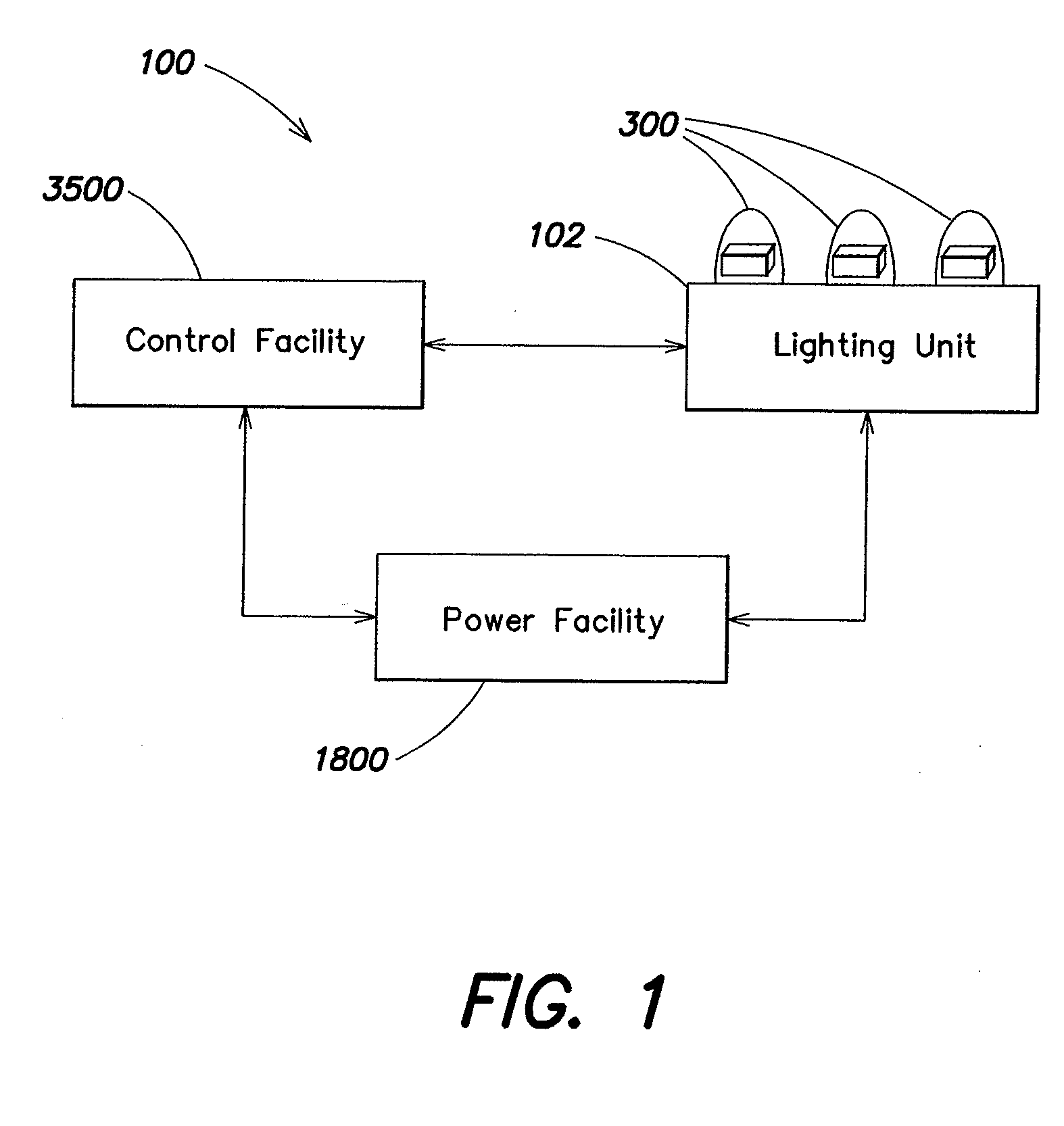
[0101] Referring to FIG. 1, in a lighting system 100 a lighting unit 102 is controlled by a control facility 3500. In embodiments, the control facility 3500 controls the intensity, color, saturation, color temperature, on-off state, brightness, or other feature of light that is produced by the lighting unit 102. The lighting unit 102 can draw power from a power facility 1800. The lighting unit 102 can include a light source 300, which in embodiments is a solid-state light source, such as a semiconductor-based light source, such as light emitting diode, or LED.

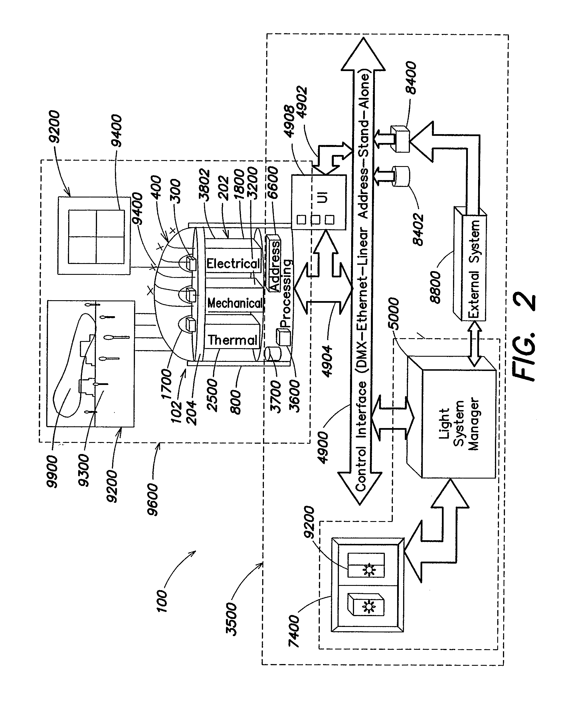
[0102] Referring to FIG. 2, the system 100 can be a solid-state lighting system and can include the lighting unit 102 as well as a wide variety of optional control facilities 3500.

[0103] In embodiments, the system 100 may include an electrical facility 202 for powering and controlling electrical input to the light sources 300, which may include drive hardware 3802, such as circuits and similar elements, and the power facility...


PUM


Abstract

Methods and systems are provided for lighting systems, including high output linear lighting systems for various environments. The linear lighting systems may include power systems for driving light sources in high-voltage environments.

Description

CROSS-REFERENCE TO RELATED APPLICATIONS [0001] This application claims the benefit under 35 U.S.C. §120 as a continuation of U.S. Non-provisional application Ser. No. 10 / 839,765, filed May 5, 2004, entitled “Lighting Methods and Systems.”[0002] Ser. No. 10 / 839,765 in turn claims the benefit, under 35 U.S.C. § 119(e), of U.S. Provisional Application Ser. No. 60 / 467,847, filed May 5, 2003, entitled “LED SYSTEMS.”[0003] The foregoing applications are incorporated herein by reference.BACKGROUND [0004] LED lighting systems are known that provide illumination and direct view effects. Most LED lighting systems require specialized power supplies that may require specialized installation and maintenance. For example, many LED lighting fixtures require a separate power supply for each fixture, which can be very inconvenient for large scale installations, such as on building exteriors. A need exists for lighting systems that provide the benefits of other LED lighting systems but provide for mo...

Claims


Application Information

Patent Timeline
IPC IPC(8): H05B39/00H05B44/00B60Q1/00B60Q1/06F21K99/00F21S2/00F21S4/00F21V1/00F21V7/04F21V13/00F21V21/00F21V29/00H05K
CPCF21K9/00F21V29/75H05B37/0245F21V15/013F21V21/30F21W2111/027F21W2111/047F21W2111/08F21W2121/004F21W2121/04F21W2131/401F21Y2103/003F21Y2105/001Y10S362/80F21Y2101/02F21V29/507F21V29/745G06F3/1446F21Y2105/10F21Y2103/10F21Y2115/10H05B47/175H05B45/345H05B45/33H05B45/355H05B45/335H05B45/37H05B45/325H05B45/3578
Inventor ROBERGE, BRIANPIEPGRAS, COLINHYER, JEFFREYMCCORMICK, KEVINSWAI, PETERMORGAN, FREDERICK
Owner SIGNIFY NORTH AMERICA CORP
Why Eureka
Try Eureka