Wireless Power System With A Self-regulating Wireless Power Receiver
a wireless power receiver and wireless power technology, applied in the direction of transformers, batteries, data exchange, etc., can solve the problems of receivers taking a considerable amount of time, fcc part 15 subpart c compliance testing becomes difficult, and it is not desirable to have a wide range of wireless power transfer frequency of operation, etc., to achieve fast response time, reduce the cost of wireless power transmission, and reduce the cost of wireless transmission
- Summary
- Abstract
- Description
- Claims
- Application Information
AI Technical Summary
Benefits of technology
Problems solved by technology
Method used
Image
Examples
first embodiment
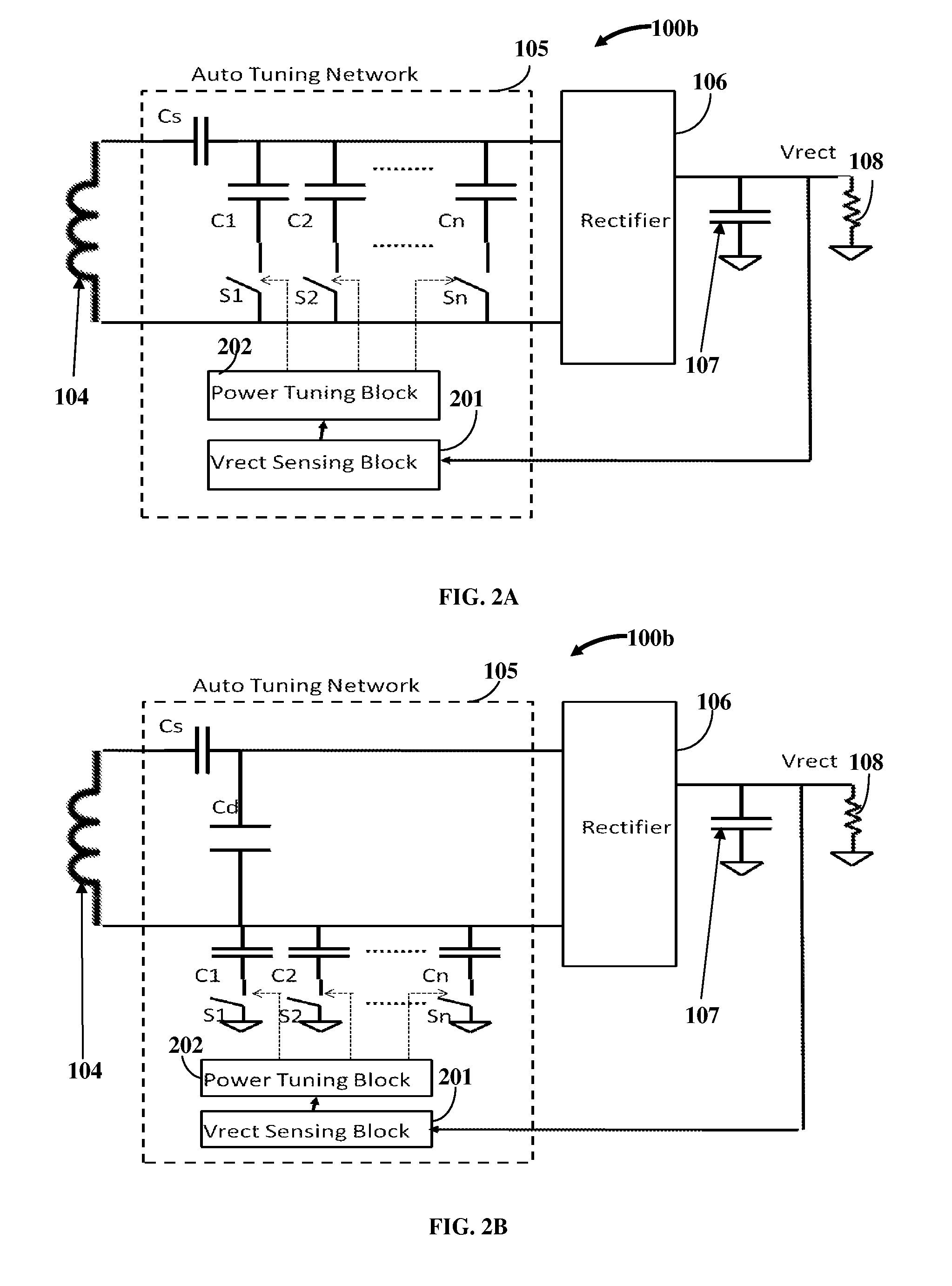
[0022]FIG. 2A exemplarily illustrates the auto-tuning network 105 of the self-regulating wireless power receiver 100b. In this embodiment, the auto-tuning network 105 includes a Vrect sensing block 201, a power tuning block 202, a series resonant capacitor Cs, and a parallel switch-capacitor network consisting of “n” parallel capacitors C1, C2, . . . , Cn and “n” switches S1, S2, . . . , Sn. In this embodiment, the parallel switch-capacitor network is connected across two alternating current (AC) IOs of the rectifier 106. The Vrect sensing block 201 measures the rectifier output voltage Vrect constantly or periodically. The power tuning block 202 compares the measured voltage Vrect with its configured threshold levels. Based on the comparison, the power tuning block 202 activates switches S1, S2, . . . , Sn. The switches may be turned on or turned off or may be pulsed on and off at a certain frequency and duty cycle. When a switch S1, S2, . . . , Sn is turned on, the associated capa...
second embodiment
[0023]FIG. 2B exemplarily illustrates the auto-tuning network 105 of the self-regulating wireless power receiver 100b. In this embodiment, the auto-tuning network 105 includes a Vrect sensing block 201, a power tuning block 202, a series resonant capacitor Cs, a parallel resonant capacitor Cd, and a parallel switch-capacitor network consisting of “n” parallel capacitors C1, C2, . . . , Cn and “n” switches S1, S2, . . . , Sn. In this embodiment, the parallel switch-capacitor network is connected asymmetrically between one of the alternating current (AC) IOs of the rectifier 106 and ground. The Vrect sensing block 201 measures the rectifier output voltage Vrect constantly or periodically. The power tuning block 202 compares the measured voltage Vrect with its configured threshold levels. Based on the comparison, the power tuning block 202 activates switches S1, S2, . . . , Sn. The switches may be turned on or turned off, or may be pulsed on and off at a certain frequency and duty cycl...
third embodiment
[0024]FIG. 2C exemplarily illustrates the auto-tuning network 105 of the self-regulating wireless power receiver 100b. In this embodiment, the auto-tuning network 105 includes a Vrect sensing block 201, a power tuning block 202, a series resonant capacitor Cs, a parallel resonant capacitor Cd, a first parallel switch-capacitor network consisting of “n” parallel capacitors C1, C2, . . . , Cn and “n” switches S1, S2, . . . , Sn, and a second parallel switch-capacitor network consisting of “n” parallel capacitors D1, D2, . . . , Dn and “n” switches E1, E2, . . . , En. In this embodiment, the two parallel switch-capacitor networks in combination together are connected symmetrically between both the alternating current (AC) IOs of the rectifier 106 and ground. The Vrect sensing block 201 measures the rectifier output voltage Vrect constantly or periodically. The power tuning block 202 compares the measured voltage Vrect with its configured threshold levels. Based on the comparison, the p...
PUM
 Abstract
Description
Claims
Application Information
 - R&D
- Intellectual Property
- Life Sciences
- Materials
- Tech Scout
- Unparalleled Data Quality
- Higher Quality Content
- 60% Fewer Hallucinations
Browse by: Latest US Patents, China's latest patents, Technical Efficacy Thesaurus, Application Domain, Technology Topic, Popular Technical Reports.
© 2025 PatSnap. All rights reserved.Legal|Privacy policy|Modern Slavery Act Transparency Statement|Sitemap|About US| Contact US: help@patsnap.com


