
Network quality of service management

a network quality and service technology, applied in the field of communication networks, can solve the problems of inability to provide qos guarantees in terms of bounds on delay, jitter and loss, and packet networks, in particular best-effort ip networks, inherently suffer from variable delay, jitter and loss, and achieve efficient and reliable response tim

Inactive Publication Date: 2009-10-27
WSOU INVESTMENTS LLC
View PDF14 Cites 113 Cited by
  • Summary
  • Abstract
  • Description
  • Claims
  • Application Information

AI Technical Summary

Benefits of technology

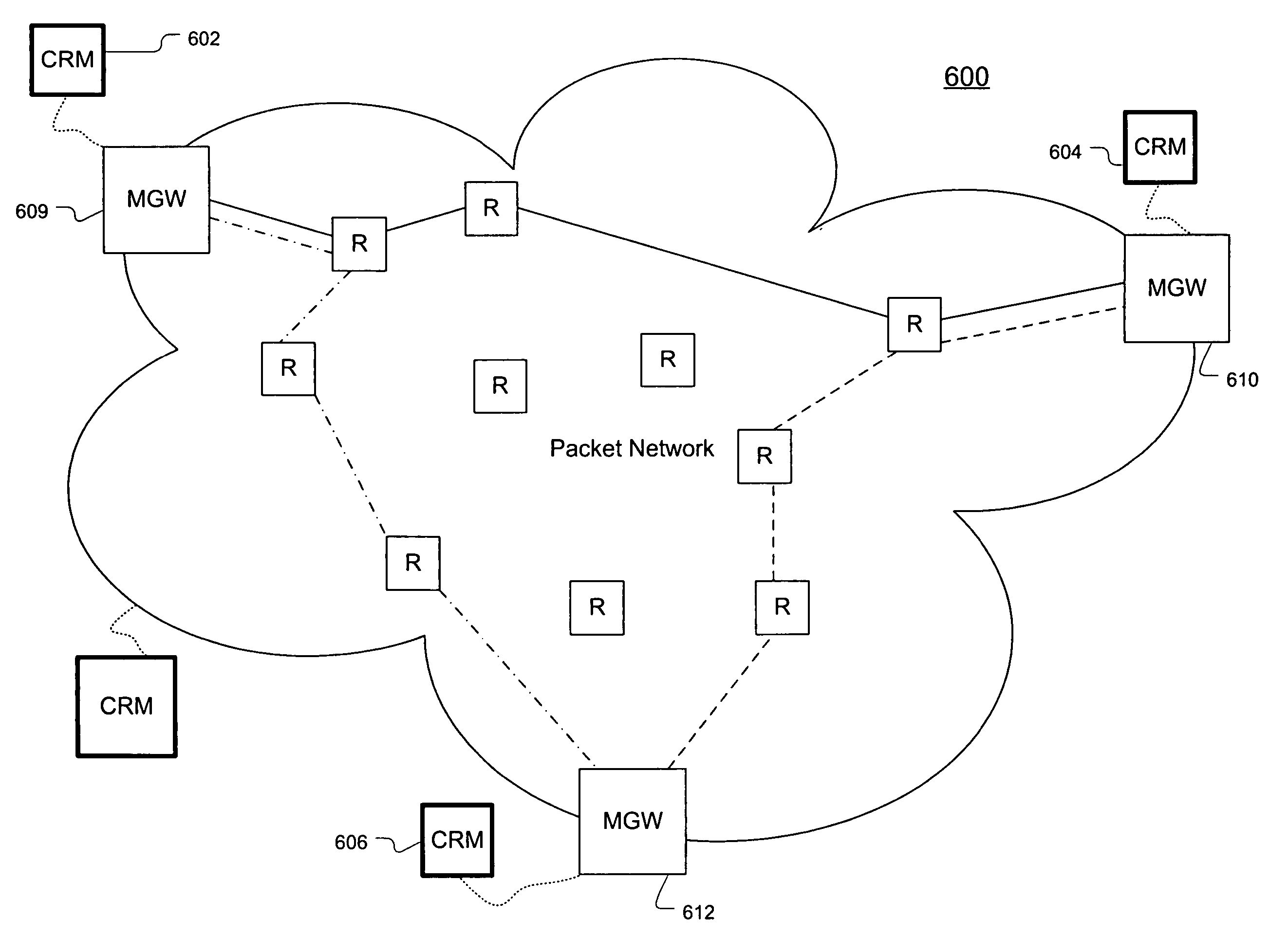
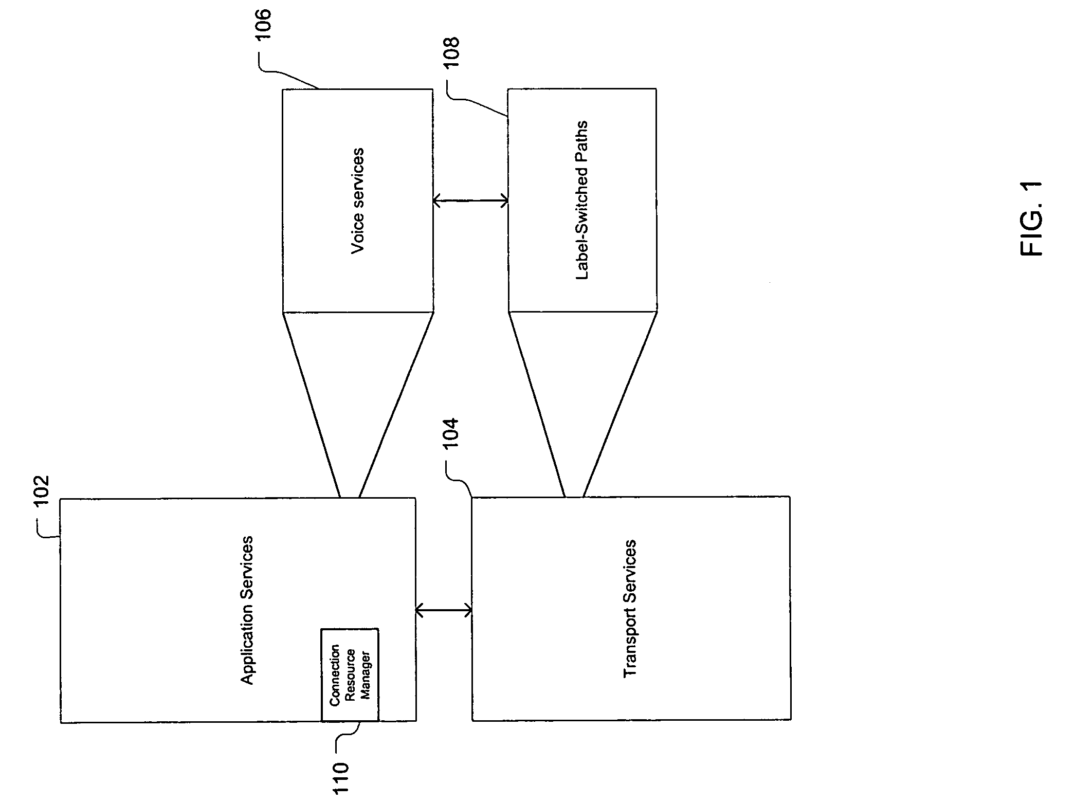
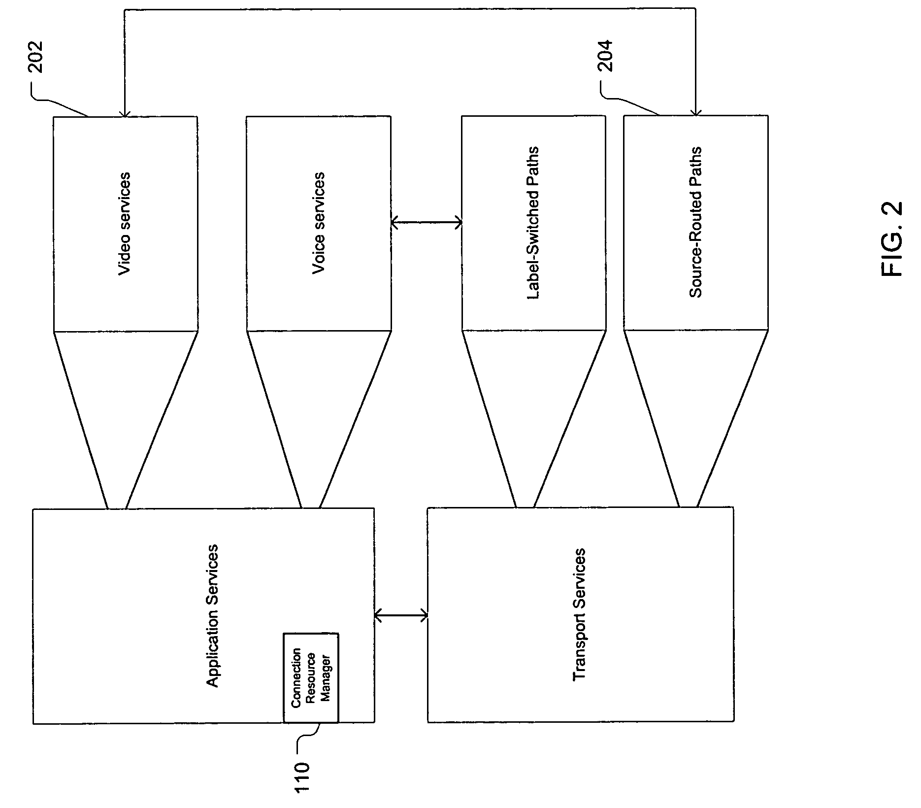
[0007]As used herein, a demand is defined as a fundamental unit of a service, such as voice, which is characterized by a required bandwidth, a source, and a destination. A QoS-sensitive demand is a demand that is sensitive to certain network attributes, including packet throughput, delay, jitter, and loss. Examples of QoS-sensitive demands include voice calls and priority emails. Problems in the prior art are addressed, in accordance with principles of the present invention, by a method and apparatus for transporting quality-of-service (QoS)-sensitive demands across a packet network by overlaying a logical circuit-switched network onto the packet network. The logical circuit-switched network brings circuit-switched QoS, such as that exhibited by the public switched telephone network (PSTN), to the packet network while retaining the dynamic resource allocation flexibility and fast response times of the underlying packet network infrasture. The logical circuit-switched network provides transport for the QoS-sensitive demands across the packet network and can provide, for example, efficient and reliable transport of voice services over an Internet protocol (IP) packet network or an asynchronous transfer mode (ATM) network by guaranteeing bandwidth and providing upper bounds (e.g., guaranteed and probabilistic) on packet delay / jitter, and a guaranteed upper bound on packet loss ratio.

Problems solved by technology

Packet networks, on the other hand, do not dedicate resources to a “connection” and are thus subject to contention among connections.
Many packet networks use best-effort techniques to support data “connections” and they typically fail to provide QoS guarantees in terms of bounds on delay, jitter, and loss.
Packet networks, in particular best-effort IP networks, inherently suffer from variable delay, jitter, and loss that may violate some QoS requirements of QoS-sensitive applications.
Signaling in packet networks, when employed, might address the notification of connection failure or congestion, but the signaling does not address comprehensive QoS management and efficient utilization of resources in providing guaranteed QoS services.
For example, when best-effort IP networks carry voice services, accepted calls can experience degradation in QoS or even failure, and the accepted calls can degrade other calls that were already in progress.

Method used


Image

  • Network quality of service management
  • Network quality of service management
  • Network quality of service management

Examples


embodiment 400

[0117]In this embodiment, illustrated by FIG. 4, VTGs are created between all pairs of communicating media gateways to carry packet voice streams. Note that significant flexibility exists in the present invention with regard to VTG creation. For example, multiple VTGs can be created between a given pair of nodes in the network. These VTGs can follow the same path or follow different paths. Since in many applications, VTGs are bidirectional, they are typically provisioned as a pair of half-duplex VTGs, one in each direction. However, in some embodiments, the two half-duplex pairs need not be the same size (bandwidth capacity). They also need not follow the same path. A forward VTG can follow one path and a return VTG could follow a different path. Also, two unidirectional VTGs could potentially be provisioned in one direction while only one is the other direction. This latter variant could support, asymmetrical transport of QoS-sensitive demands such as video-casting, for example. Ot...

embodiment 900

[0139]FIG. 9 illustrates a hierarchical embodiment 900 of the present invention. As illustrated, the MSWs are divided into three clusters 902, 904, and 906, where each cluster is managed by its own CRM (908, 910, and 912, respectively) at the first level of the hierarchy. Within each cluster, one of the MSWs is designated to be a core MSW (C-MSW) 918. The three C-MSWs 918 (one from each cluster) are themselves interconnected by a set of VTGs 916. The C-MSWs and the VTGs that interconnect them are considered to form the second level of the hierarchy. A level-two CRM (914) is used to manage the level-two VTGs 916. A C-MSW plays a role similar to that of an MSW in the sense that a C-MSW can be hosted by edge routers and use packet-network service-level assurances (SLAs) to create VTGs between them. However, C-MSWs are connected by VTGs in level-two areas. Each C-MSW provides a connectivity point from any MSW in its local level-one area to all other level-one areas. Thus, every MSW in a...


PUM


Abstract

An architecture for quality-of-service (QoS) management creates a logical circuit-switched network within a packet network to support QoS-sensitive demands levied on the network. This QoS-managed network can serve to interwork, e.g., a PSTN with VoIP networks. The architecture can include a connection resource manager (CRM), which oversees bandwidth availability and demand admission / rejection on dynamically provisioned virtual trunk groups (VTGs) within the packet network, and a transport bandwidth controller (TBC). The VTGs serve to transport QoS-sensitive demands across the packet network. The TBC serves the CRM by providing an interface to routers and / or OAM systems of the packet network to size VTGs to meet QoS requirements. Media switches located at the packet network borders serve to mux / demux the demands into / from VTGs. CRMs and TBCs can be implemented as centralized, distributed, or hierarchical, and flat and aggregated variants of the architecture are supported. VTGs can be implemented using MPLS LSPs, VPNs, or source-based routing.

Description

CROSS-REFERENCE TO RELATED APPLICATIONS[0001]This application claims the benefit of the filing date of U.S. provisional application No. 60 / 549,818, filed on Mar. 3, 2004.BACKGROUND OF THE INVENTION[0002]1. Field of the Invention[0003]The present invention relates to communications networks and, more specifically, to quality-of-service (QoS) management for QoS-sensitive services in communications networks, such as voice-over-Internet protocol (VoIP) services.[0004]2. Description of the Related Art[0005]Circuit-switched networks, such as the public switched telephone network (PSTN), utilize signaling to establish call connections along a path between a call's source and its destination. Each call connection uses a time slot on each link in its path and each switch maps a call from an input port and / or time slot to an output port and / or time slot. The selection of time slots and mappings happens during the call setup signaling. Once a call is established, these slots are dedicated to t...

Claims


Application Information

Patent Timeline
Patent Type & Authority Patents(United States)
IPC IPC(8): H04L1/00
CPCH04L47/825H04L47/805H04L47/78H04L47/783H04L45/34H04L45/50H04L47/782H04L47/781
Inventor DOSHI, BHARAT T.SAMADI, BEHROKHWANG, YUNG-TERNG
Owner WSOU INVESTMENTS LLC
Learn More