Time division modulation with average current regulation for independent control of arrays of light emitting diodes

a technology of time division modulation and independent control, which is applied in the direction of electric variable regulation, process and machine control, instruments, etc., can solve the problems of low efficiency of power conversion, low efficiency of series pass current regulator, and multi-stage power, and achieve the effect of reducing the cost of controllers and faster response tim

Active Publication Date: 2011-03-08
CHEMTRON RES
View PDF5 Cites 116 Cited by
  • Summary
  • Abstract
  • Description
  • Claims
  • Application Information

AI Technical Summary

Benefits of technology

[0012]Providing such local regulation of LED arrays is a significant advance compared to the prior art use of a central, overall system (or host) computer or microprocessor for certain types of remote regulation. The local regulation provided by the present invention enables a significantly faster response time, without requiring the prior art communication protocols, and further provides a more comprehensive approach for maintaining selected color and brightness levels throughout the life span of the LEDs and corresponding changes in their functional parameters. Exemplary embodiments also may be implemented using comparatively lower cost controllers. When the exemplary embodiments are further implemented to be backwards-compatible with legacy control systems, the present invention frees the host computer for other tasks and allows such host computers to be utilized for other types of system regulation.

Problems solved by technology

Such prior art multistring LED drivers typically require redundant drivers for every LED string.
This approach represents a multistage power system with low efficiency of power conversion, in addition to already low efficiency of series pass current regulators, particularly when the DC voltage is constant and does not depend on current.
In this case, an additional, current sink stage is added in series with each LED string current regulator, resulting in a further decrease in efficiency, particularly when the current sink is used to bypass the LED current to ground when the LED should be off.
This multistage power system, with dedicated current converters and controllers in each LED channel, in addition to low efficiency, has a large size, many expensive components, and is expensive to manufacture.
This proposal has several significant problems: (1) the system is very complex, inefficient (for power conversion), has many expensive components, and is expensive to manufacture; (2) the current to emission (color) transfer function in emitting diodes is substantially nonlinear, leading to a poor color control or requiring additional, undisclosed technical means for compensation of this nonlinearity (not suggested in the patent); and (3) the disclosed current source operates poorly, suffering from thermal dependency and requiring correction by a microprocessor.
The referenced prior art with multi-output or separate power converters and controllers for each LED string of an LED array increases the cost and size of the LED driver, and reduces the functionality and efficiency of the driver.

Method used


Image

  • Time division modulation with average current regulation for independent control of arrays of light emitting diodes
  • Time division modulation with average current regulation for independent control of arrays of light emitting diodes
  • Time division modulation with average current regulation for independent control of arrays of light emitting diodes

Examples


example 1

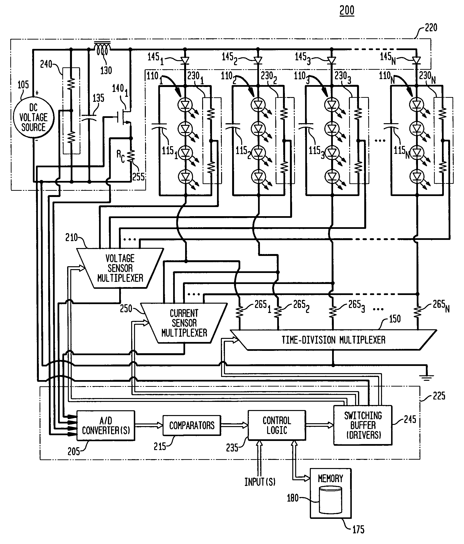
[0058]For a system having three series of LEDs 1101, 1102, and 1103, with average channel currents are initially set as Ic1=500 mA, Ic2=520 mA, and Ic3=480 mA, then Ic500+520+480=1500 mA. Assuming Tc=1000 μs and T=1 μs, under the control of the controller 125 directing switching through multiplexer 150, the power converter 120 will supply to each channel a current of 1500 mA for the run times

[0059]TQ⁢⁢1=500·10001500=333⁢⁢μs,⁢TQ⁢⁢2=520·10001500=347⁢⁢μs,andTQ⁢⁢3=480·10001500=320⁢⁢μs

which will result in the following number of cycles of the power converter 120: m1=333, m2=347, and m3=320.

[0060]Continuing with the example, we may now suppose that for any of various reasons, such as a,change in junction temperature, a change in color output, etc., the current in channel one (series of LEDs 1101) only is to be adjusted to 275 mA, while the previous current levels are to be maintained in the remaining channels 2 and 3 (series of LEDs 1102 and series of LEDs 1103). Accordingly, the total av...

example 2

[0063]For a continuous conduction mode (“CCM”), as illustrated in FIG. 5,

[0064]Ic=Ip⁢⁢1⁢i+Ip⁢⁢2⁢i2·tr⁢⁢1T,

where[0065]Ip1i—First peak current, Channel i;[0066]Ip2i—Second peak current, Channel i; and[0067]tri—reset time, Channel i.

Two variables are introduced for ease of explanation and derivation of equations, as follows:

[0068]ai=Ip⁢⁢2⁢iIp⁢⁢1⁢i,

namely, the ratio of the second peak current to the first peak current for a selected ith channel, and

[0069]bi=triT,

namely, the ratio of the switch 140 reset time (i.e., off or open time) to the total cycle time, resulting in a first peak current for an ith channel of:

[0070]Ip⁢⁢1⁢i=2⁢Ic(1+ai)⁢bi.

[0071]Another expression for the first peak current Ip1i is:

[0072]Ip⁢⁢1⁢i=Ip⁢⁢2⁢i+Vi⁢⁢n·toniL

where[0073]Vin—Input voltage from DC voltage source 105;[0074]toni—on time, Channel i; and[0075]L—inductance value of inductor 130.

With substitutions

[0076]Ip⁢⁢1⁢i=Vin·toni(1-ai)⁢L

then one more expression for Ip1i current is

[0077]Ip⁢⁢1⁢i=Ip⁢⁢2⁢i+(Vouti-Vin)·tri...

example 3

[0084]For a discontinuous conduction mode (“DCM”), as illustrated in FIG. 6, peak current Ip1i is defined as

[0085]Ip⁢⁢1⁢i=2⁢Ic⁢Ttri

Also, for a boost configuration using DCM:

[0086]Ip⁢⁢1⁢i=Vin·toniL

and volt-seconds balance across inductor 130 is:

Vin·toni=(Vouti−Vin)·tri

The peak current Ip1i is then:

[0087]Ip⁢⁢1⁢i=2⁢Ic·VoutiVin

[0088]The technique of generating the value of the output voltage Vouti is the same as described above for CCM of operation. The boundary between CCM and DCM may be found analytically by solving the following equation, or by determining if the actual cycle time, after current discharge by the inductor 130 is completed, is equal to the set cycle time T:

[0089]T=2⁢Ic⁢LVouti2Vin2⁡(Voui-Vin)

[0090]The amplitude of voltage ripple ΔVi in a selected channel i is given by the following relationship, from which the capacitance values of capacitors 115 may be determined:

[0091]Δ⁢⁢Vi=Ic·TQi2Ci·Tc

[0092]Referring again to FIG. 3, the controller 125 receives one or more inputs fr...


PUM


Abstract

Exemplary apparatus, method and system embodiments provide for separately and independently sourcing current to a series of light emitting diodes of a plurality of series of light-emitting diodes. An exemplary apparatus comprises a power converter which generates a current, a first multiplexer, and a controller. The controller provides for sequential and separate switching of the current through the first multiplexer to each of the series of light-emitting diodes for a corresponding period of time. An average current provided by the power converter is determined as substantially equal to a sum of the corresponding currents through the plurality of series of light-emitting diodes. A total period for switching current to all of the series of light-emitting diodes is also determined. A corresponding time period for switching current to a selected corresponding series of light-emitting diodes is substantially equal to a proportion of the total period determined as a ratio of the corresponding current for the selected corresponding series of light-emitting diodes to the average current provided by the power converter.

Description

FIELD OF THE INVENTION[0001]The present invention in general is related to converters and regulators used for driving and controlling arrays of light emitting diodes and, in particular, is related to an apparatus, system and method for time division modulation with average current regulation for independent control of arrays of light emitting diodes.BACKGROUND OF THE INVENTION[0002]Arrays of light emitting diodes (“LEDs”) are utilized for a wide variety of applications, including for ambient lighting. To achieve emission of light perceived as white light, LED arrays typically utilize a combination of red, green and blue (“RGB”) LEDs (and, occasionally, amber LEDs), usually as a first series connection (a first “string”) of a plurality of red LEDs, a second series connection (a second string) of a plurality of green LEDs, and a third series connection (a third string) of a plurality of blue LEDs, typically which are referred to as “multistring LEDs”.[0003]For driving an array of LEDs...

Claims


Application Information

Patent Timeline
Patent Type & Authority Patents(United States)
IPC IPC(8): H05B37/00H05B44/00
CPCH05B33/0815H05B33/0818H05B33/083H05B33/0869H05B33/0827Y02B20/347H05B45/46H05B45/24H05B45/38Y02B20/30H05B45/3725H05B45/48H05B45/22
Inventor SHTEYNBERG, ANATOLYRODRIGUEZ, HARRY
Owner CHEMTRON RES
Why Eureka
Try Eureka