Fundus camera

a technology of fundus camera and camera body, which is applied in the field offundus camera, can solve the problems of demerit for a handheld type of fundus camera, difficult focusing, complicated whole structure, etc., and achieve the effect of reducing irresolution, compact apparatus, and efficient alignment operation

Inactive Publication Date: 2007-06-28
NIDEK CO LTD
View PDF22 Cites 31 Cited by
  • Summary
  • Abstract
  • Description
  • Claims
  • Application Information

AI Technical Summary

Benefits of technology

[0015] As describe above, and in accordance with the present invention, the apparatus enables a target projection for focusing upon observing,and enables a removal of the target projection upon photographing without providing such a complicate optical system or moving mechanism. Consequently, the compactness and lightening of the apparatus can be achieved.
[0016] Also, in accordance with the p

Problems solved by technology

As a result of this, the focusing was very difficult by only judging such a fundus image.
Also, since another mechanism of withdrawing the oblique mirror at photographing was needed, it resulted in a disadvantage that the whole structure was complicate.
In view of this problem, i

Method used


Image

  • Fundus camera
  • Fundus camera
  • Fundus camera

Examples


Embodiment Construction

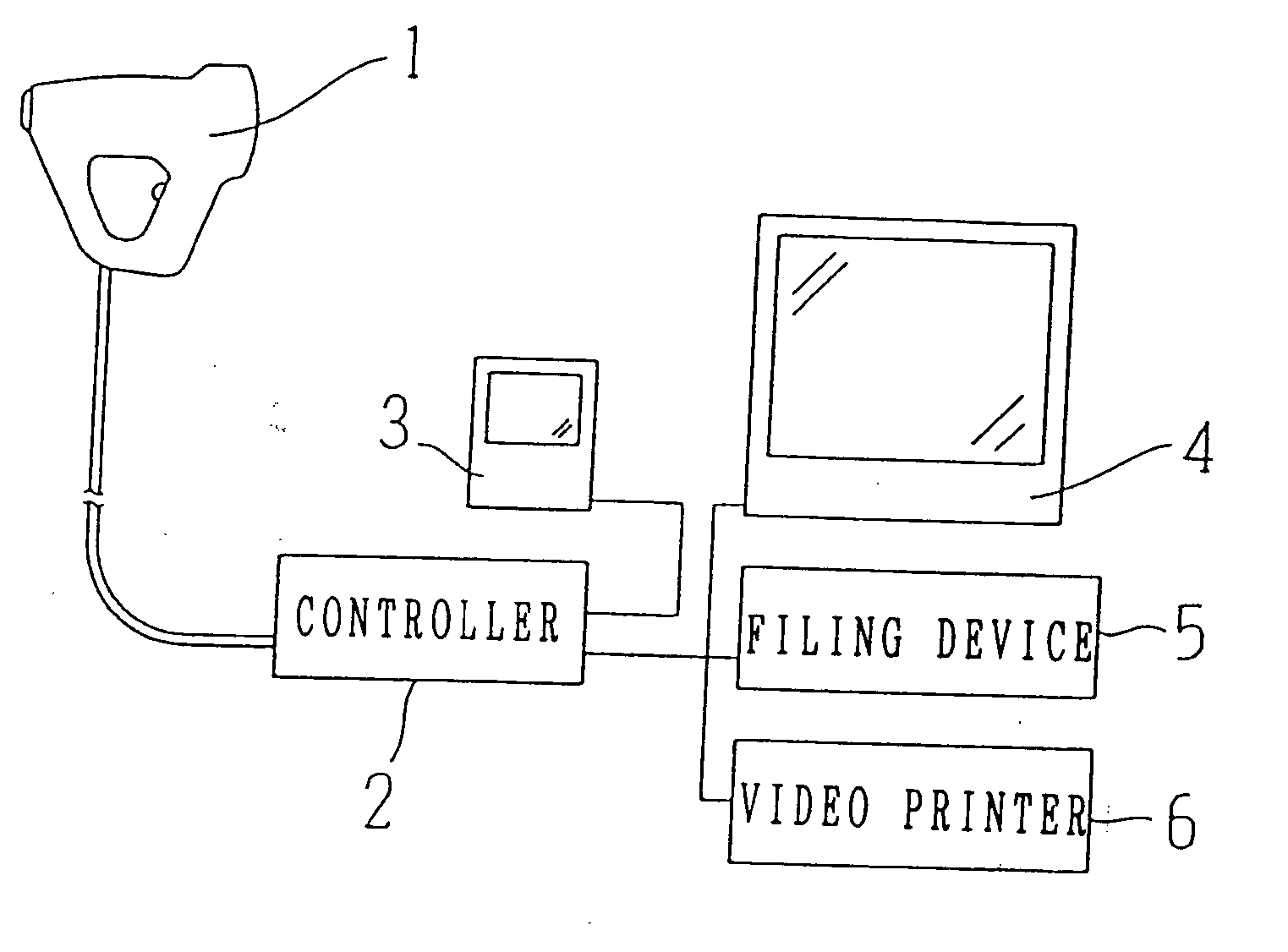
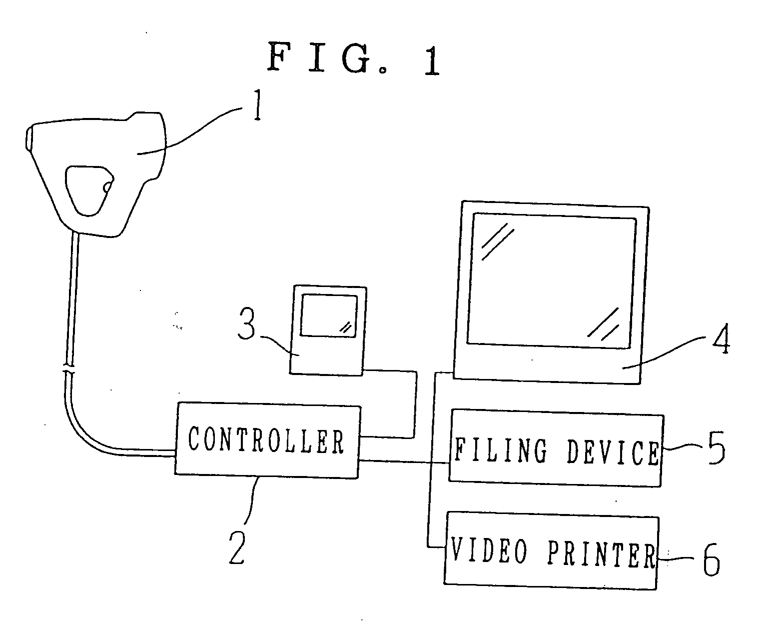
[0024] A detailed description of the present invention is provided below with reference to the accompanying drawing. FIG. 1 is a view showing an outline structure of a fundus camera of the preferred embodiment. The fundus camera of the preferred embodiment is generally structured by a photographing unit 1 storing an optical system and the like for observing and photographing into a body suitable for a hand-held operation, a controller 2 for controlling the photographing unit 1, an observation monitor 3, a display monitor 4, a filing device 5 and a video printer 6, and also each section is connected electrically.

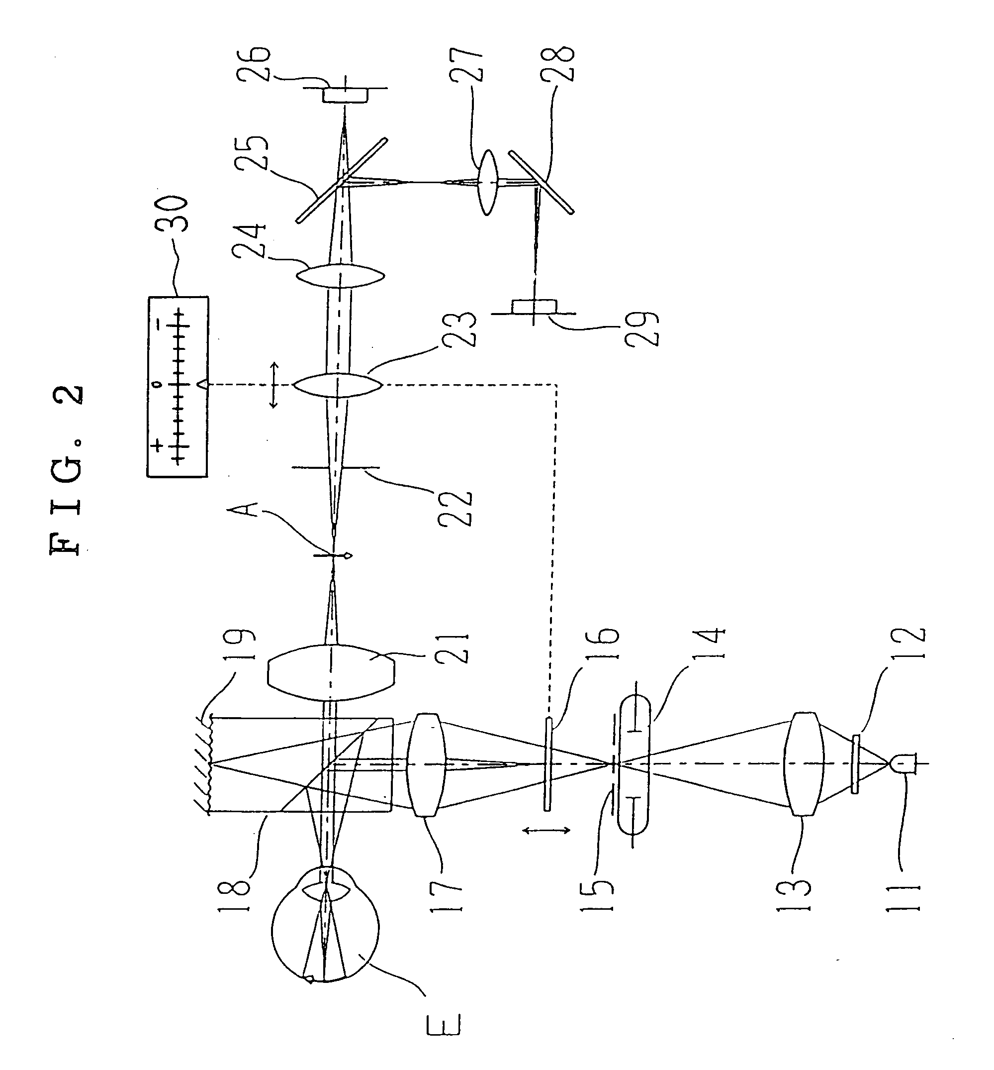
[0025]FIG. 2 is a view showing a detailed structure of optical system of the fundus camera. The optical system will be described herein by dividing into the illumination / target projection optical system and the observation / photographing optical system separately.

(Illumination / Target Projection Optical System)

[0026] An infrared light emitting diode 11 is an illumination li...


PUM


Abstract

A fundus camera having a photographing optical system for photographing a fundus of an eye to be examined, the camera providing, a first illumination optical system for illuminating the fundus of the eye with using infrared light, a second illumination optical system for illuminating the fundus of the eye with using visible light for photography by sharing a part of optical path with the first illumination optical system, a target projecting optical system for projecting a target for focusing on the fundus of the eye, an observation optical system provided with a focusing lens and photographic element having sensitivity in an infrared area, for observing the fundus of the eye which is illuminated by the infrared light of the first illumination optical system and a target image of a target plate projected on the fundus of the eye, displaying device for displaying an image obtained by the observation optical system, moving device for moving by interlocking the focusing lens of the observation optical system and the target plate, travel-distance displaying device for displaying travel distances by the moving device.

Description

CROSS—REFERENCE TO RELATED APPLICATIONS [0001] This application is a continuation application of U.S. patent application Ser. No. 08 / 960,825 filed on Oct. 30, 1997 now on appeal.BACKGROUND OF THE INVENTION [0002] 1. Field of the Invention [0003] The present invention relates to a fundus camera for photographing a fundus of an eye to be examined, and more particularly to a focusing mechanism of the fundus camera suitable for focusing a fundus image illuminated by an infrared light. [0004] 2. Description of Related Art [0005] The conventional fundus camera for photographing the fundus of the eye has been well-known as a non-mydriasis method of photographing the fundus image by using an infrared light as an illumination light for observation without using an additional medicine like a mydriatica. However, since the fundus image illuminated by the infrared light mainly seemed to be an image of blood vessel, the whole image was less contrasty and indistinct. As a result of this, the focu...

Claims


Application Information

Patent Timeline
IPC IPC(8): G03B13/00
CPCA61B3/14A61B3/12
Inventor NANJO, TSUGUO
Owner NIDEK CO LTD
Why Eureka
Try Eureka