Novel mydriasis-free portable fundus camera

A camera and lighting system technology, applied in fundus mirrors, eye testing equipment, medical science, etc., can solve problems such as troublesome design and complexity

Active Publication Date: 2012-09-26
BEIJING INSTITUTE OF TECHNOLOGYGY
View PDF5 Cites 28 Cited by
  • Summary
  • Abstract
  • Description
  • Claims
  • Application Information

AI Technical Summary

Problems solved by technology

The traditional method of eliminating the stray light generated by the reflection of the cornea and the eye lens is relatively complicated, and the design is cumbersome, requiring complex calculations and adjustments

Method used


Image

  • Novel mydriasis-free portable fundus camera
  • Novel mydriasis-free portable fundus camera
  • Novel mydriasis-free portable fundus camera

Examples


Embodiment 1

[0028] The zoom data of embodiment 1 is as shown in table 2:

[0029] Table 2

[0030]

-8D

-5D

0D

3D

5D

8D

10D

object distance

-125

-200

Infinity

333

200

125

100

Image distance (visible light)

10.40

10.56

10.81

10.97

11.08

11.24

11.37

Image distance (near infrared)

10.50

10.66

10.91

11.07

11.18

11.34

11.47

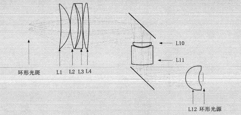
[0031] image 3 The illumination system of the fundus camera of the present invention is shown. like image 3 As shown, from the human eye to the light source, the sequence is the object plane, the first lens L1, the second lens L2, the third lens L3, the fourth lens L4, the diaphragm, the tenth lens L10, the eleventh lens L11, the Twelve lenses L12 and ring light.

[0032] The first lens L1 is a negative meniscus lens with negative power, which is a glass lens element ...

Embodiment 2

[0047] The zoom data of embodiment 2 is as shown in table 5:

[0048] table 5

[0049]

-8D

-5D

0D

3D

5D

8D

10D

object distance

-125

-200

Infinity

333

200

125

100

Image distance (visible light)

10.40

10.55

10.8

10.96

11.07

11.23

11.35

Image distance (near infrared)

10.50

10.65

10.9

11.06

11.178

11.33

11.45

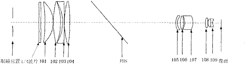
[0050] Figure 8 Embodiment 3 imaging system of the present invention is shown. like Figure 8 As shown, from the human eye to the CCD receiving surface are (from left to right) 1 / 4 wave plate, diaphragm, first lens 301, second lens 302, third lens 303, fourth lens 304, PBS, the first lens Fifth mirror 305, sixth mirror 306, seventh mirror 307, eighth mirror 308, ninth mirror 309, CCD receiver.

[0051] The first lens 301 is a negative meniscus lens with negative power, ...

Embodiment 3

[0058] The zoom data of embodiment 3 is as shown in table 7:

[0059] Table 7

[0060]


PUM


Abstract

The invention provides a fundus camera optical system for detecting lesion of human eyes, and particularly provides a novel mydriasis-free portable fundus camera. The novel mydriasis-free portable fundus camera comprises a lighting system and an imaging system. The imaging system comprises an eye objective lens and an imaging objective lens, wherein the eye objective lens consists of first, second, third and fourth lenses from left to right, the imaging objective lens consists of fifth, sixth, seventh, eighth and ninth lenses, fundus is imaged on a CCD (Charge Coupled Device) by the imaging system and displayed in real time by an LCD (Liquid Crystal Display). The lighting system consists of an annular light source, a dodging lens and an eye objective lens, wherein the dodging lens consists of tenth, eleventh and twelfth lenses, and the eye objective lens and the imaging system are commonly used. PBS (Phosphate Buffer Solution) and a quarter wavelength plate are added in the system so as to eliminate the ghost image generated by the eye objective lens. According to the invention, the 2-megapixel CCD is adopted as the camera, the MTF (Mechanical Time Fuse) value is larger than 0.2 at a position of 120lp/mm, the full field angle is 60 degrees, the distortion value is smaller than 5%, and the fundus camera can be universally applicable to human eyes of minus 8D to positive 10D through adjusting the positions of the CCD.

Description

technical field [0001] The invention designs a fundus camera used for detecting human eye lesions in the range of visible light and near infrared. Background technique [0002] The fundus camera mainly includes two parts: imaging system and lighting system. The objective lens is shared by the imaging system and the lighting system. How to uniformly illuminate the fundus and how to eliminate the stray light caused by the reflection of the cornea and the objective lens are the difficulties in the design of the fundus camera. [0003] At present, the widely used fundus camera adopts the method of adding annular diaphragm and hollow mirror to obtain annular light spot at the pupil, and eliminates the influence of reflected light produced by the cornea on imaging by controlling the inner and outer diameters of the annular light spot. Eliminate the ghost images in the illumination light path caused by the reflection of each surface of the eyepiece objective lens by adding a black...

Claims


Application Information

Patent Timeline
Patent Type & Authority Applications(China)
IPC IPC(8): A61B3/15A61B3/12
Inventor 程德文杨加强王庆丰刘越王涌天
Owner BEIJING INSTITUTE OF TECHNOLOGYGY
Why Eureka
Try Eureka