

Video coding device, video decoding device and video encoding method
a video coding and video technology, applied in the field of video coding devices, video decoding devices and video encoding methods, can solve the problems of reducing the coding efficiency of video
- Summary
- Abstract
- Description
- Claims
- Application Information
AI Technical Summary
Problems solved by technology
Method used
Image

Examples
first embodiment
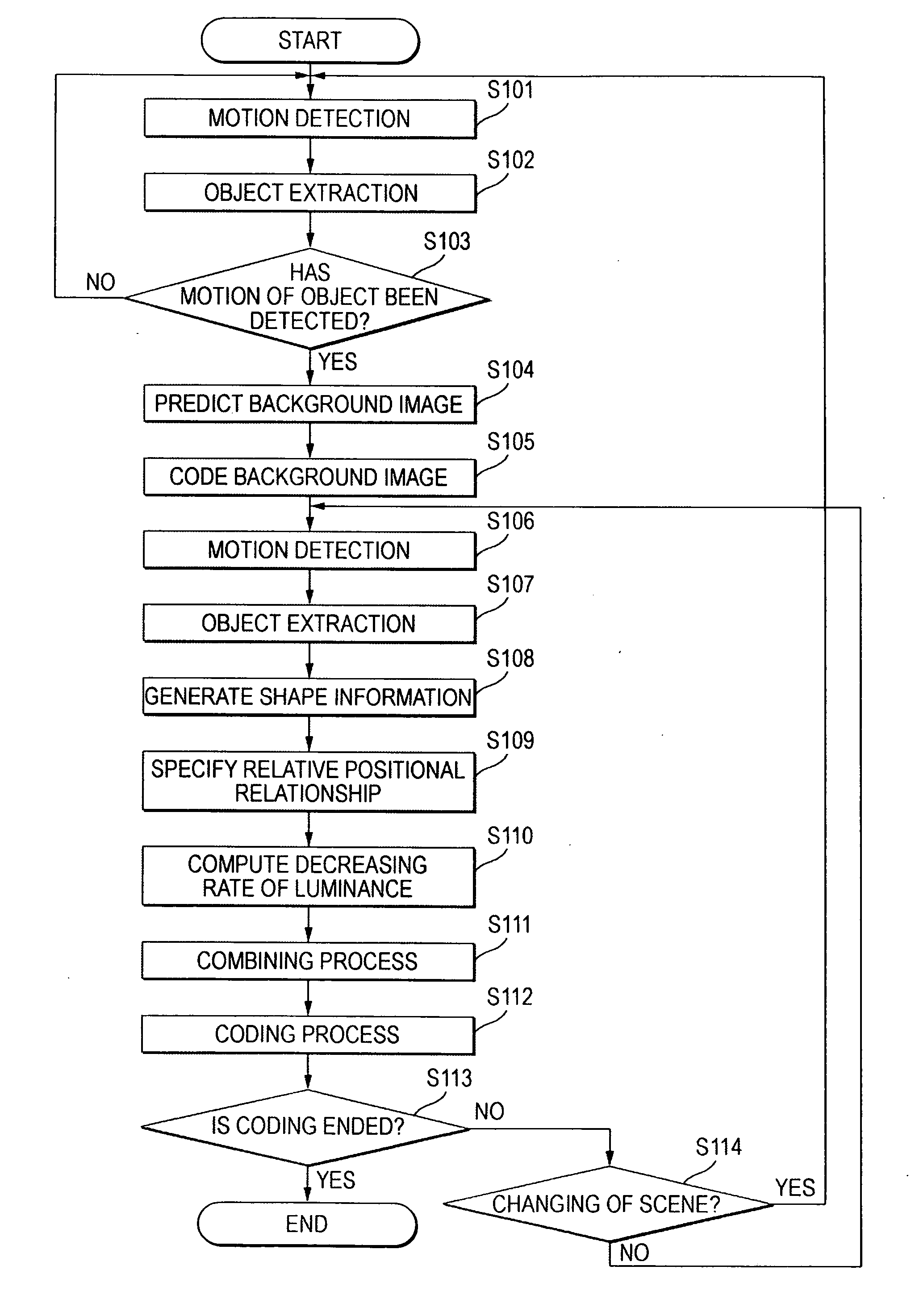
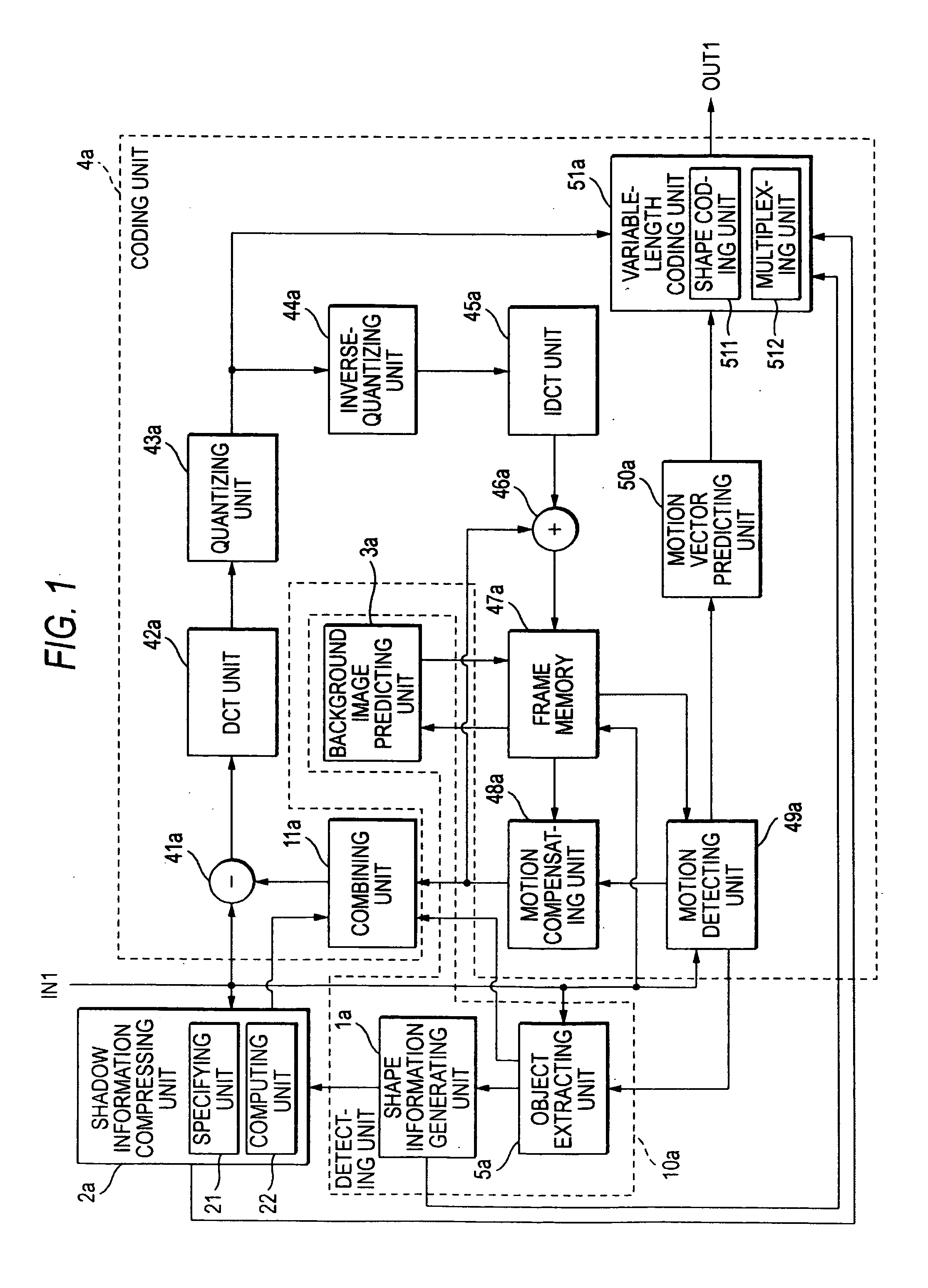
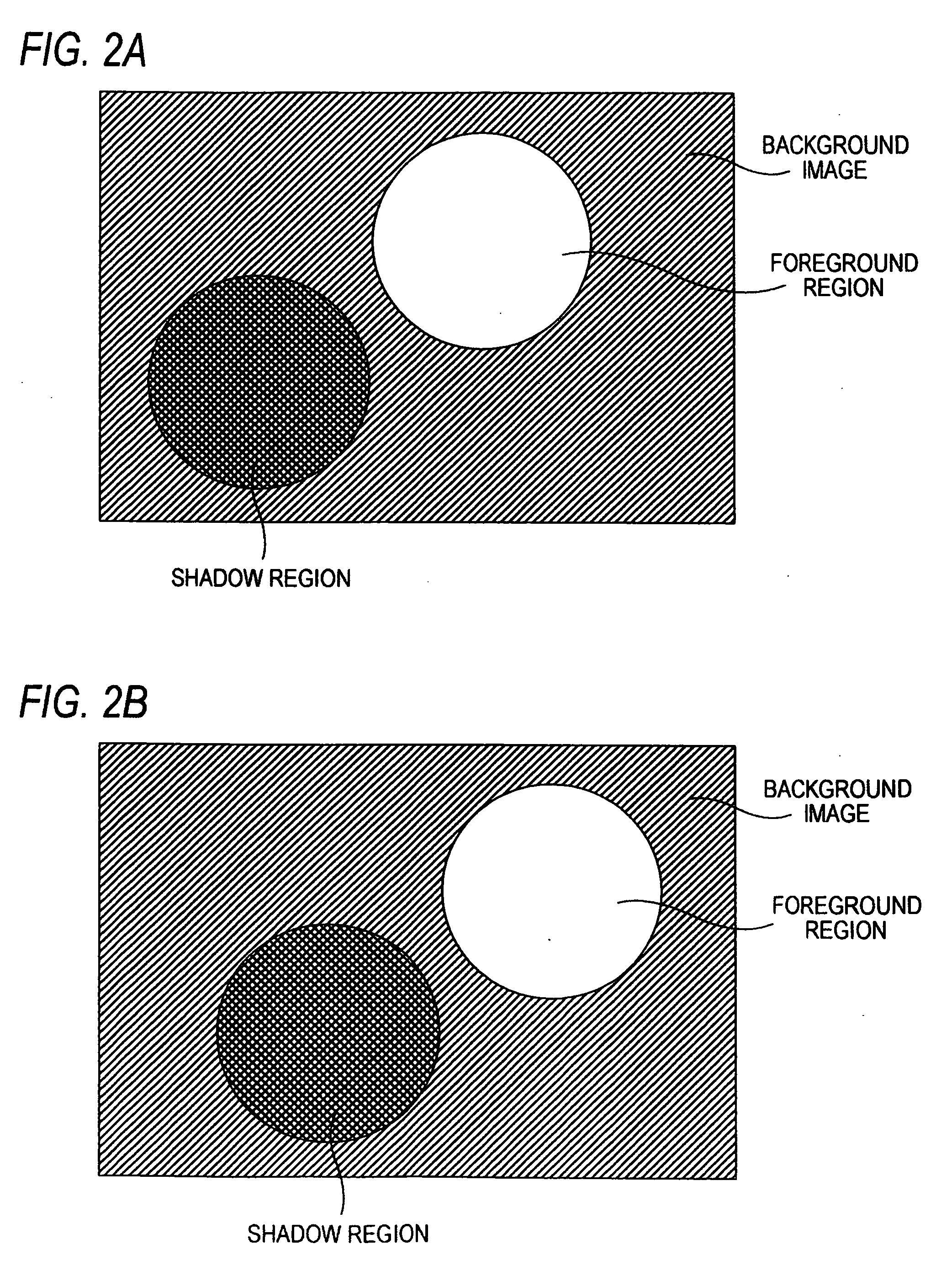
[0021] As shown in FIG. 1, the video coding device according to the first embodiment of the invention is configured to code a video containing a series of input pictures IN1. The video coding device includes a detecting unit 10a, a shadow information compressing unit 2a, and a coding unit 4a. The detecting unit 10a detects a foreground region, a background image and a shadow region reflected on the background image by the foreground region in each of the input pictures IN1. The shadow information compressing unit 2a performs compression process for compressing the information quantity of the shadow region. The coding unit 4a codes information on the foreground region, the background image and the shadow region subjected to the compression process. Now, the “foreground region” means a region of the object which is a target to be picked up in the input picture IN1. The “background image” means the image of the background defined by a region except the foreground region and the shadow ...
second embodiment
[0054] In the second embodiment of the invention, an explanation will be given of a video decoding device capable of decoding the video coded by the video coding device shown in FIG. 1. As shown in FIG. 6, the video decoding device according to the second embodiment is configured to decode a video from a coded bit stream IN2 as an input. The coded bit stream IN2 includes coded pictures each containing a foreground region, a background image and a shadow region reflected on the background image by the foreground region. The video decoding device includes a decoding unit 60, a restoring unit 65, and combining unit 67. The decoding unit 60 decodes, from the coded bit stream IN2, the background image, shape information of the foreground region, information of the relative positional relationship between the foreground region and the shadow region, and information of the decreasing rate of luminance of the shadow region relative to the background image. The restoring unit 65 restores the...
third embodiment
[0065] In the video coding device according to the third embodiment of the invention, an explanation will be given of a video decoding device relied on the coding system not using the shape coding technique, e.g. MPEG2 or H.264 (MPEG AVC). As shown in FIG. 8, in the video coding device according to the third embodiment, the shadow information compressing unit 2b performs the compression process for the shadow region in the input picture IN1 and supplies the input picture of the shadow region subjected to the compression process to the subtracter 41b. The coding unit 4b does not perform the process for the shape coding. Further, a detecting unit 10b does not have the shape information generating unit la as shown in FIG. 1. The remaining arrangement is the same as in the video coding device shown in FIG. 1.
[0066] The video coding device shown in FIG. 8 intends to improve the coding efficiency by changing the information on the shadow region. The shadow information compressing unit 2b...
PUM
 Abstract
Description
Claims
Application Information