Connection Systems for Two Piece Prosthetic Heart Valve Assemblies and Methods for Using Them

a technology of connecting system and heart valve, which is applied in the field of connecting system of multiple component heart valve, can solve the problems of increasing reducing the chance of errors, and reducing the chance of complications

Inactive Publication Date: 2007-06-28
MEDTRONIC INC
View PDF53 Cites 133 Cited by
  • Summary
  • Abstract
  • Description
  • Claims
  • Application Information

AI Technical Summary

Benefits of technology

[0013] In accordance with still another embodiment, a heart valve assembly is provided that includes a first annular prosthesis including an annular member implantable within a biological annulus, a sewing cuff extending outwardly from the annular member, and a plurality of connectors extending inwardly from the sewing cuff, and a second valve prosthesis including an annular frame including a plurality of receptacles, e.g., windows, for receiving respective connectors therein to secure the second valve prosthesis relative to the first prosthesis.

Problems solved by technology

The sewing rings of either type of prosthetic valve can be tedious and time consuming to secure within a target site, i.e., within an annulus of a heart where a natural heart valve has been removed.
Consequently, this procedure can be very complicated, requiring management and manipulation of many sutures.
The complexity of the procedure also provides a greater opportunity for mistakes and requires a patient to be on cardiopulmonary bypass for a lengthy period of time.
Because the annulus of the heart may not match the circular cross-section of the sewing ring and / or prosthetic valve, the prosthetic valve may not fit optimally within the annulus.
As a result, natural blood hemodynamics through and around the valve may be impaired, resulting in clotting, possible emboli production, and eventual calcification of the valve structure.
When a mechanical or prosthetic valve is then attached to the sewing ring, however, the valve and sewing ring may not mate together effectively, e.g., if the shape of the sewing ring has been distorted to conform to the annulus, which may also impair natural blood hemodynamics, create leaks, and / or otherwise impair performance of the prosthetic valve.

Method used


Image

  • Connection Systems for Two Piece Prosthetic Heart Valve Assemblies and Methods for Using Them
  • Connection Systems for Two Piece Prosthetic Heart Valve Assemblies and Methods for Using Them
  • Connection Systems for Two Piece Prosthetic Heart Valve Assemblies and Methods for Using Them

Examples


Embodiment Construction

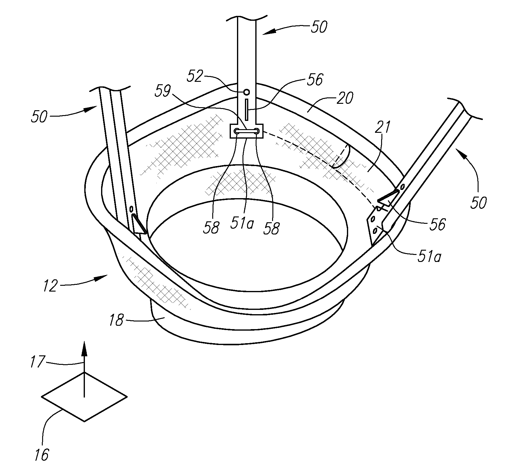
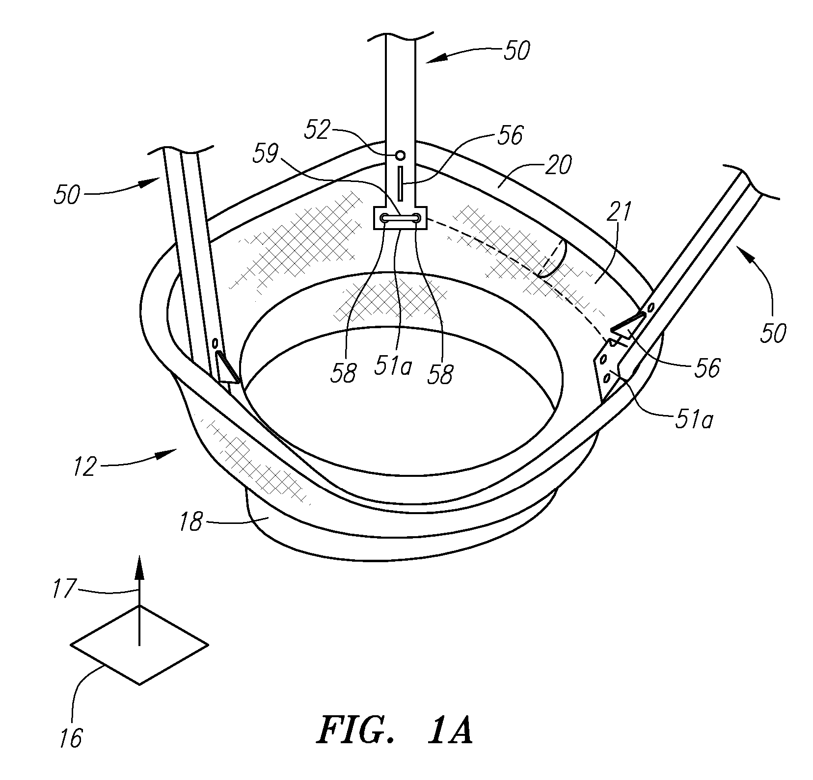
[0040] Turning to the drawings, FIGS. 1A and 2A show an embodiment of a gasket member 12 and a valve member 14, respectively, that may be combined to provide a heart valve assembly 10, e.g., as shown in FIGS. 6A and 6B.

[0041] As shown in FIG. 1A, the gasket member 12 generally includes an annular ring 18, a sewing cuff 20, and a plurality of guide rails or other elements 50 extending from the sewing cuff 20 or other portion of the gasket member 12, as described further below. Optionally, the gasket member 12 may also include a flexible skirt and / or baleen elements (not shown), e.g., surrounding a lower portion of the annular ring 18. A fabric covering 21 may be provided on one or more components of the gasket member 12, e.g., over the annular ring 18 and / or over a core of the sewing cuff 20.

[0042] In one embodiment, the annular ring 18 may have a generally circular shape generally parallel to plane 16, and / or may include an undulating shape relative to longitudinal axis 17. Altern...


PUM


Abstract

A heart valve assembly includes a prosthesis for receiving a prosthetic valve to replace a preexisting natural or prosthetic heart valve within a biological annulus adjacent a sinus cavity. The prosthesis includes an annular member, a sewing cuff extending radially outwardly from the annular member and a plurality of guide rails extending from the prosthesis. The prosthetic valve includes an annular member, at least one valve and receptacles for receiving the guide rails. Locking tabs positioned on the guide rails engage with locking windows in the receptacles to attach the prosthetic valve with the prosthetic valve.

Description

RELATED APPLICATION DATA [0001] This application claims benefit of co-pending application Ser. No. 60 / 748,639, filed Dec. 7, 2005, the entire disclosure of which is expressly incorporated herein by reference.FIELD OF THE INVENTION [0002] The present invention relates generally to heart valves that may be implanted within a patient, and, more particularly, to connection systems for multiple component heart valves that may be assembled together, and to apparatus and methods for using them. BACKGROUND [0003] Prosthetic heart valves can replace defective human valves in patients. For example, one piece valves have been suggested that include sewing rings or suture cuffs that are attached to and extend around the outer circumference of a prosthetic valve. In addition, multiple component valves have also been suggested that include a sewing ring that is separate from a valve component. The sewing rings of either type of prosthetic valve can be tedious and time consuming to secure within a...

Claims


Application Information

Patent Timeline
Patent Type & Authority Applications(United States)
IPC IPC(8): A61F2/24
CPCA61F2/2409A61F2/2412A61F2/2427A61F2002/30428A61F2002/30611A61F2220/0025A61F2250/0063A61F2002/30604
Inventor GURSKIS, DONNELL W.LANE, EMESTINO, TAKASHI HARRY
Owner MEDTRONIC INC
Why Eureka
Try Eureka