
Modular laundry system with work surface

a laundry system and work surface technology, applied in the field of modular laundry systems, can solve the problems of inefficiency, small laundry area, inconvenient operation, etc., and achieve the effect of preventing vibration transfer

Inactive Publication Date: 2007-07-05
WHIRLPOOL CORP
View PDF99 Cites 19 Cited by
  • Summary
  • Abstract
  • Description
  • Claims
  • Application Information

AI Technical Summary

Benefits of technology

[0023] The worksurface can comprise a vibration dampener configured to prevent transference of vibration between the at least two laundry appliances and the worksurface.

Problems solved by technology

A common complaint of homeowners is that the laundry area tends to be an afterthought when the home is designed.
Many feel that the laundry area is small, poorly arranged, and inefficient.
Regardless of size, the laundry area is not optimized for performing functions other than the conventional washing and drying done in the washer and dryer, such as flat drying, hang drying, ironing, hand steaming, spot pre-treatment, stain removal, and the like.
This configuration meets the basic needs of doing laundry but neither provides facilities for performing other functions nor optimizes the process of doing laundry.
For example, some clothes need to be hung or laid flat to dry after washing, but there is usually no dedicated space for these items.
This process is extremely inconvenient and time consuming, especially if only one garment needs to be touched up.
Additionally, the laundry area typically does not provide flat surfaces that can be employed for, for example, applying stain pre-treatments, flat drying clothing items, or for folding clothes after they have been dried.
Conventional laundry appliances provide a flat surface, but the surface is not particularly suited for some of these tasks.
Further, the space between horizontally arranged laundry appliances can be annoying if such tasks are conducted on top of the laundry appliances, and clothing items can fall in the space between the laundry appliances.
However, these solutions are not ideal; some are inconvenient to store when not in use, others are not dimensioned to optimize the space of the laundry area, and all are not aesthetically coherent with the laundry appliances.

Method used


Image

  • Modular laundry system with work surface
  • Modular laundry system with work surface
  • Modular laundry system with work surface

Examples


Embodiment Construction

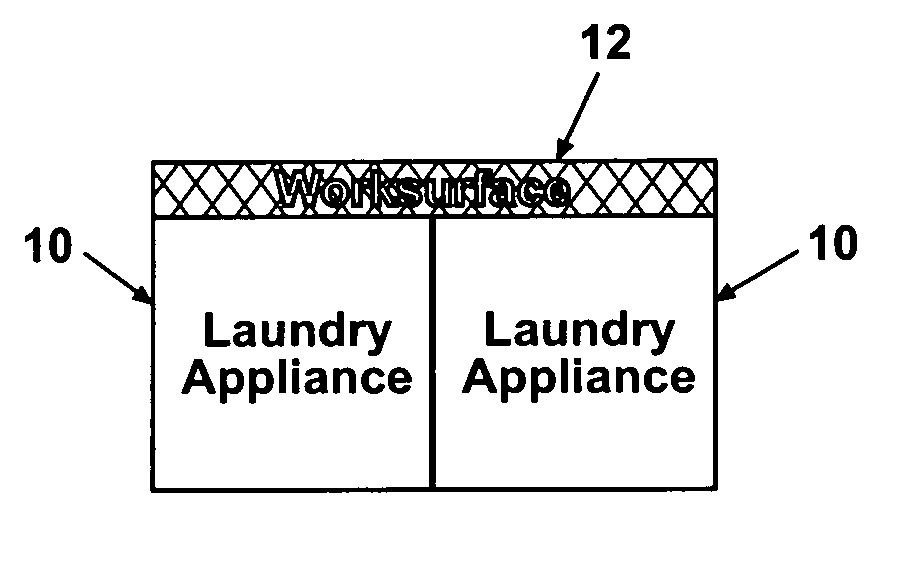
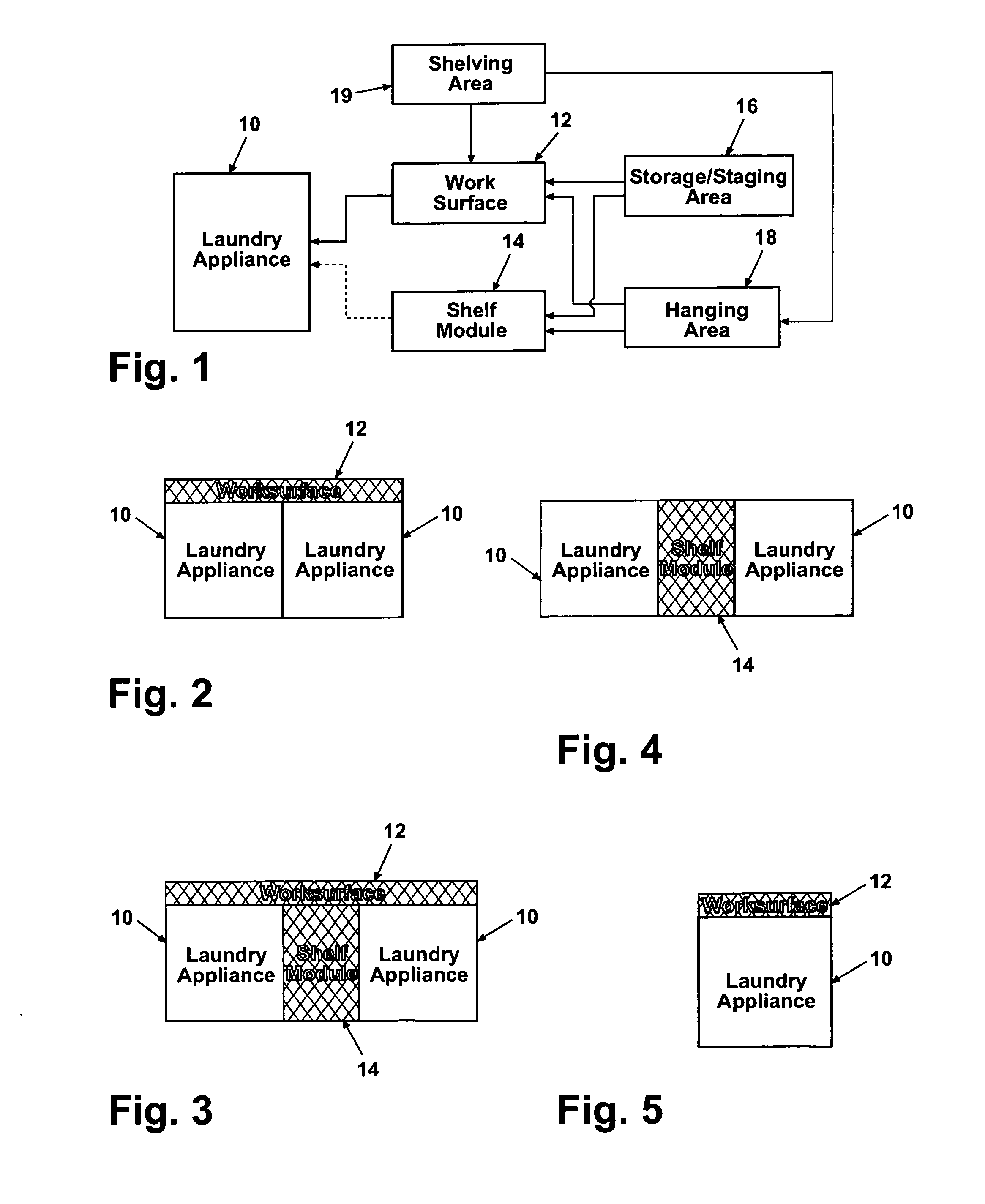
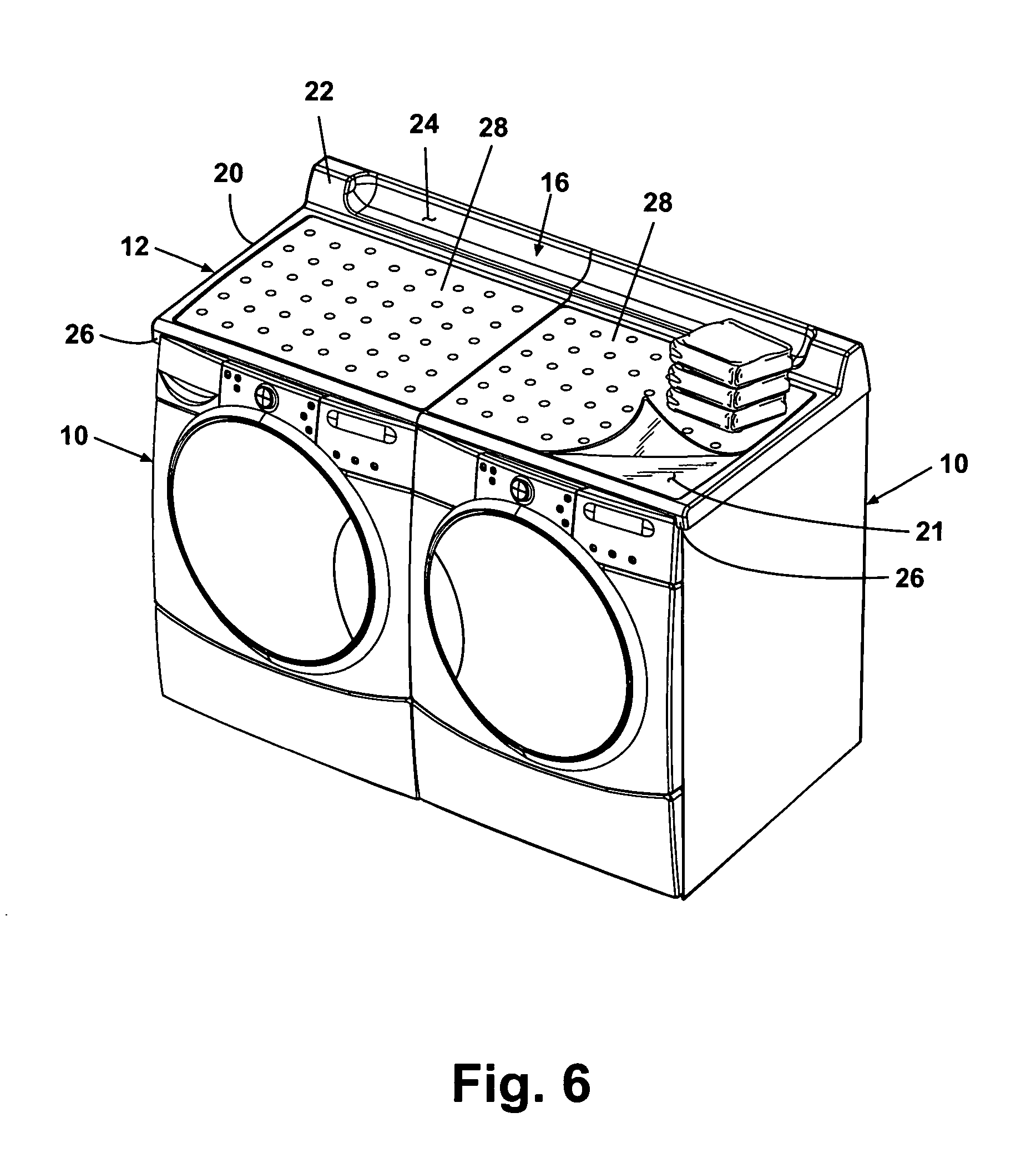
[0112] A modular laundry system according to one embodiment of the invention comprises at least one laundry appliance 10 and a worksurface 12. The modular laundry system can optionally comprise a shelf module 14 in addition to the worksurface 12 or instead of the worksurface 12. Each of the worksurface 12 and the shelf module 14 can optionally have at least one of a storage / staging area 16 and a hanging area 18. The worksurface 12 can further include a shelving area 19, which is inherent in the shelf module 14. According to one embodiment of the invention, the modular laundry system comprises two laundry appliances 10 and at least one of the worksurface 12 and the shelf module 14, which can be selected and configured to provide desired laundry care functionality within a given laundry area. The laundry area is a space of a home in which the laundry appliance 10 conventionally resides. The laundry area can be, for example, a dedicated laundry room, a shared room, such as a combined l...


PUM


Abstract

A modular laundry system comprises at least two horizontally arranged laundry appliances. Each of the at least two laundry appliances have a top, and a worksurface extends over the tops of the at least two laundry appliances. The worksurface can form a continuous surface above the at least two laundry appliances.

Description

BACKGROUND OF THE INVENTION [0001] 1. Field of the Invention [0002] The invention relates to a modular laundry system comprising at least one laundry appliance and an associated worksurface and / or an optional shelf module that can be configured to spatially and functionally optimize a household laundry area. [0003] 2. Description of the Related Art [0004] Most homeowners utilize laundry appliances, such as a washer and a dryer, to clean clothing and other fabric items. The laundry appliances are located in a household laundry area that can be a dedicated laundry room, a laundry closet, or part of another room or hallway of the home. A common complaint of homeowners is that the laundry area tends to be an afterthought when the home is designed. Many feel that the laundry area is small, poorly arranged, and inefficient. [0005] Regardless of size, the laundry area is not optimized for performing functions other than the conventional washing and drying done in the washer and dryer, such...

Claims


Application Information

Patent Timeline
Patent Type & Authority Applications(United States)
IPC IPC(8): D06F37/00D06F35/00D06F34/28
CPCD06F39/12D06F29/00D06F39/125D06F34/28D06F39/02D06F29/005D06F29/02A47B88/40A47B2210/17D06F37/04A47B88/42A47B88/919A47B46/005D06F81/06
Inventor GILBOE, KEVIN JAMESACHTERBERG, LORRAINE L.KENDALL, JAMES WILLIAM
Owner WHIRLPOOL CORP
Learn More