Dual detent system

a dual-detent, shift-like technology, applied in the direction of mechanical control devices, process and machine control, instruments, etc., can solve the problems of affecting shift feel, requiring complicated controls, and requiring expensive solutions, so as to reduce the occurrence of jump-outs

Inactive Publication Date: 2007-07-05
ARVINMERITOR TECH
View PDF16 Cites 4 Cited by
  • Summary
  • Abstract
  • Description
  • Claims
  • Application Information

AI Technical Summary

Benefits of technology

[0005] A vehicle transmission includes a top cover and a shift rail that is supported by the top cover. A neutral detent mechanism cooperates with the shift rail to provide a first detent force when shifting from a neutral position to a gear engaged position. A gear detent mechanism cooperates with the shift rail to provide a second detent force when shifting out of the gear engaged position. In one example, the second detent force is greater than the first detent force to reduce the occurrence of jumpout.
[0007] The shift rail includes a first detent profile that engages the first resiliently biased member and a second detent profile that engages the second resilient biased member. The first detent profile has a first contoured surface and the second detent profile has a second contoured surface. In one example, the second contoured surface has a sharper or steeper profile surface than the first contoured surface. This steeper groove surface requires a more aggressive shift force for shifting out of the gear engaged position. The first contoured surface has a more gradual or shallower groove surface that provides a good shift feel for an operator when shifting out of the neutral position and into the gear engaged position.

Problems solved by technology

This high center of gravity makes certain shift levers more prone to un-requested shifts from an in-gear position to a neutral position.
These solutions are expensive and require complicated controls.
Further, these methods can adversely affect shift feel when shifting from the neutral position to an in-gear position.

Method used


Image

  • Dual detent system
  • Dual detent system

Examples


Embodiment Construction

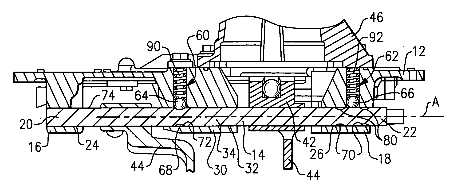
[0013] A top cover 12 and a shift rail 14 as used in a vehicle transmission (not shown) are shown in FIG. 1. The top cover 12 includes a first support member 16 and a second support member 18. The shift rail 14 includes a first end portion 20 and a second end portion 22. The first end portion 20 is supported within a bore 24 formed in the first support member 16 and the second end portion 22 is supported within a bore 26 formed in the second support member 18.

[0014] The top cover 12 also includes a central support member 30 that is positioned between the first 16 and second 18 support members. The central support member 30 includes a bore 32 that receives a center portion 34 of the shift rail 14.

[0015] The shift rail 14 defines an axis A that extends along a length of the shift rail 14. The shift rail 14 is axially moveable within the bores 24, 26, 32 in response to shift requests.

[0016] A stub lever (not shown) is coupled to the shift rail 14 to communicate shift requests from a...


PUM


Abstract

A shift rail for a vehicle transmission includes multiple detent mechanisms for shifting that operate independently from each other. The shift rail includes a neutral detent mechanism that allows shifting from a neutral position into a gear engaged position at a first detent force, and an in-gear detent mechanism that allows shifting out of a gear engaged position at a second detent force that is greater than the first detent force. By setting the second detent force higher than the first detent force, un-requested shifts out of the gear engaged position, i.e. “jumpout,” can be controlled. Additionally, the neutral and in-gear detent mechanisms include separate springs where spring forces can be varied to adjust shift feel as needed.

Description

TECHNICAL FIELD [0001] The subject invention relates to a transmission shift rail that has independent in-gear and in-neutral detents to control jumpout and allow adjustment of shift feel. BACKGROUND OF THE INVENTION [0002] Heavy-duty vehicles, such as freight hauling Class 8 trucks, have a longer shift lever than shift levers found in passenger vehicles. Longer shift levers inherently have a high center of gravity. This high center of gravity makes certain shift levers more prone to un-requested shifts from an in-gear position to a neutral position. This phenomenon is often referred to as “jumpout.”[0003] Different solutions have been used to reduce the occurrence of jumpout. One known solution provides a detent system. in combination with a control valve. The detent system includes a plunger with a tip that is received within the control valve. Pressure applied to the tip from the control valve is varied to selectively tailor detent forces. Another known solution provides a plunge...

Claims


Application Information

Patent Timeline
Patent Type & Authority Applications(United States)
IPC IPC(8): G05G5/00B60K20/00
CPCF16H63/38Y10T74/20085G05G5/065
Inventor HUMPHREY, MICHAEL K.SCHEIB, PATRICK L.PICONE, KENNETH T.
Owner ARVINMERITOR TECH
Why Eureka
Try Eureka