
Digital camera

Inactive Publication Date: 2007-07-05
FUJIFILM CORP
View PDF18 Cites 9 Cited by
  • Summary
  • Abstract
  • Description
  • Claims
  • Application Information

AI Technical Summary

Benefits of technology

[0007] It is a primary object of the present invention to provide a digital camera which facilitates camera information checking, and assures visibility of a through image.
[0008] It is another object of the present invention to provide a digital camera which improves visibility of a through image at low costs.
[0020] According to the present invention, the captured image and the camera information can be viewed on the identical display surface by changing the viewing direction between the first and second directions. Owing to this, the camera information can be easily observed. In addition, only the captured image becomes observable depending on the viewing direction. Owing to this, it is prevented that the visibility of the captured image is lowered when overlapped by the camera information. Moreover, the captured image and the camera information are displayed on one display device, and therefore production cost is reduced as compared to the digital camera with two display devices.

Problems solved by technology

When the camera information is displayed over the through image, part of the through image is replaced by the camera information, and therefore the thorough image cannot be viewed clearly and appropriately.
In the publication JP-A-2001-69397, however, providing two display devices raises production costs.
In the publication JP-A-2001-211368, the operation for switching display and nondisplay of the camera information is troublesome.

Method used


Image

  • Digital camera
  • Digital camera
  • Digital camera

Examples


Embodiment Construction

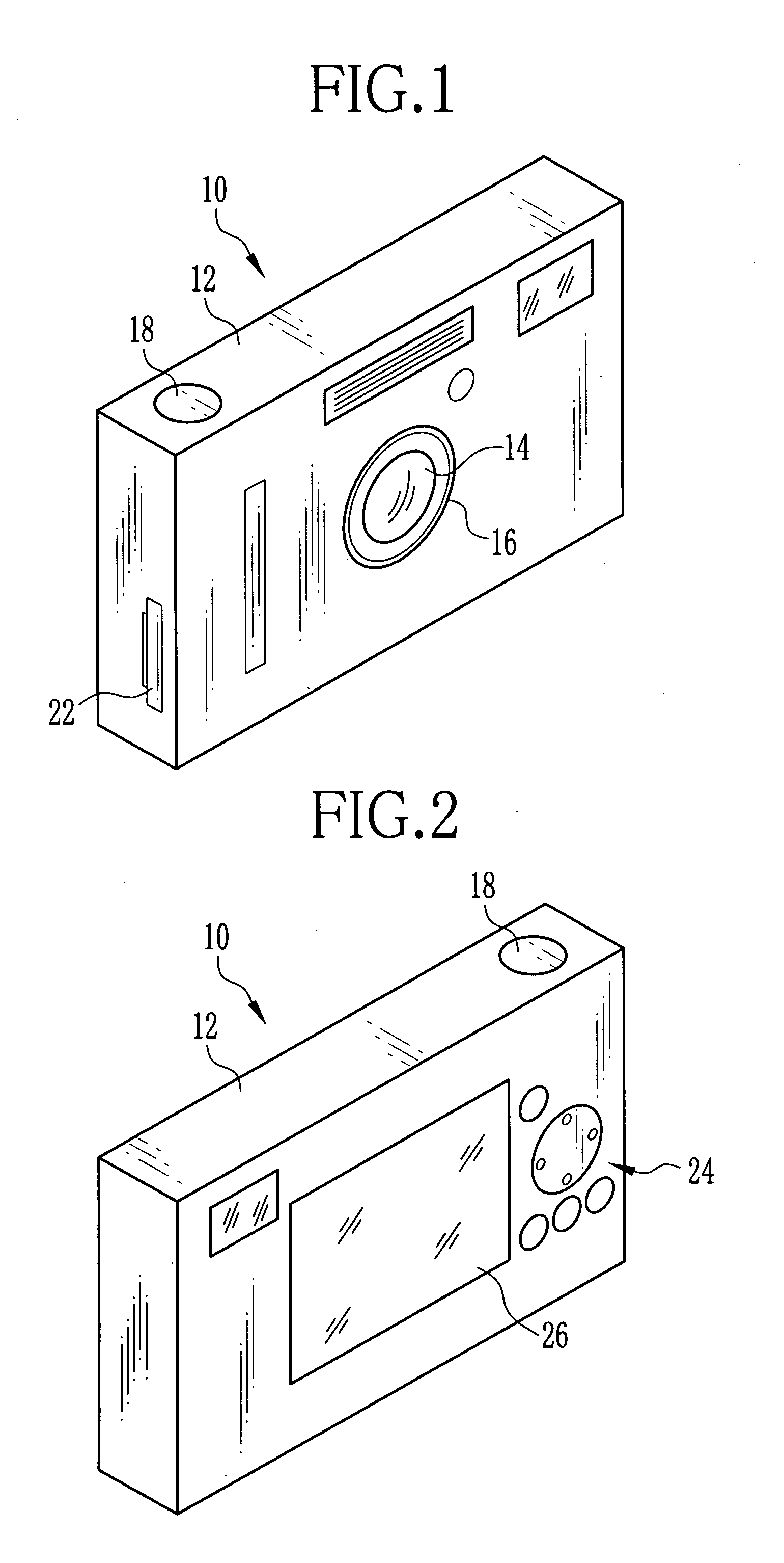
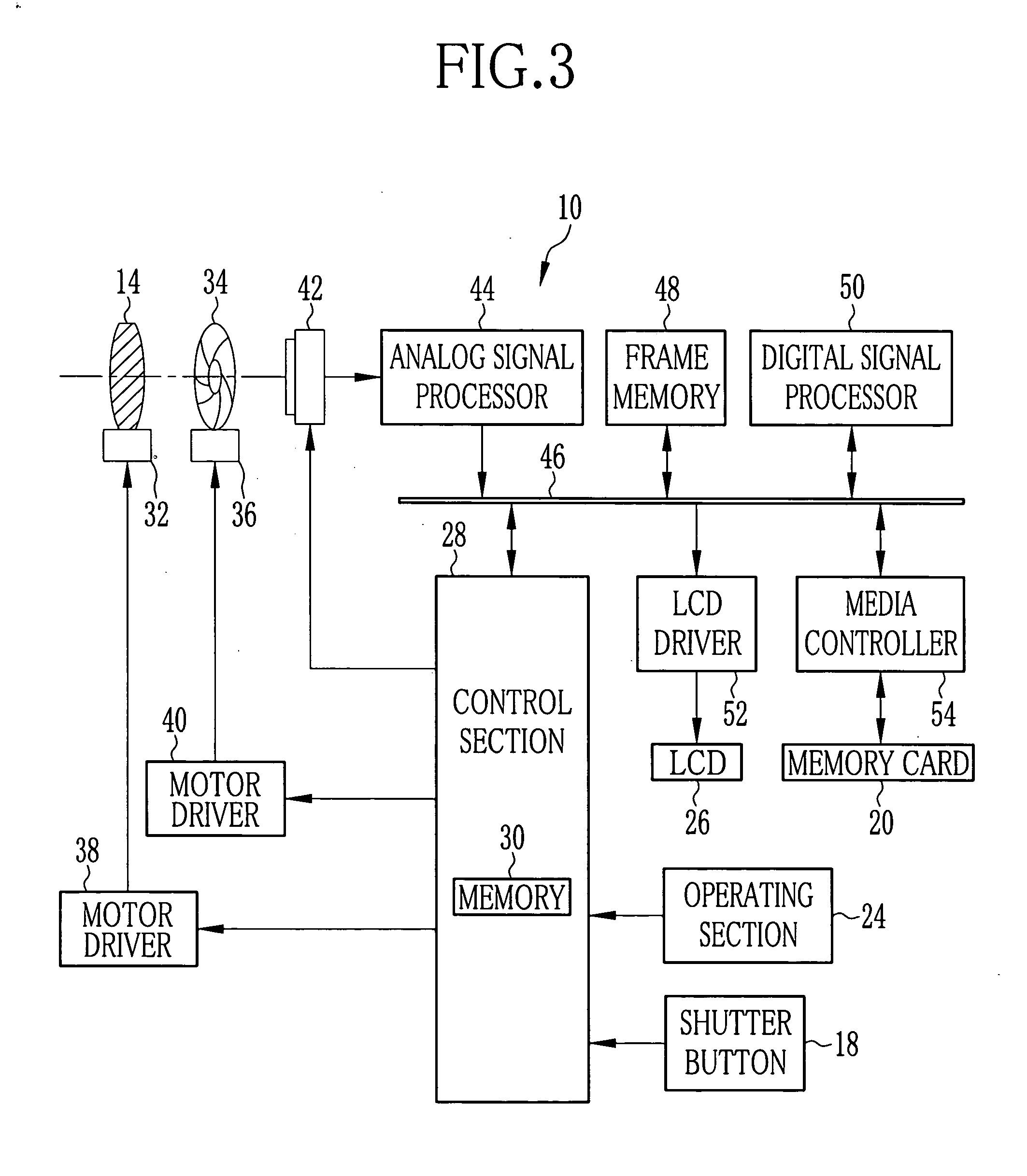
[0031] In FIG. 1, a digital camera 10 according to the present invention has a camera body 12 with a substantially rectangular parallelepiped shape. At a front surface of the camera body 12, a lens barrel 16 holding a taking lens unit 14 is disposed. At a top surface of the camera body 12, a shutter button 18 is disposed, and at a side surface of the camera body 12, a memory card slot (not shown) to which a memory card 20 (see, FIG. 3) is detachably connected and a lid 22 for closing the memory card slot are disposed. When the digital camera 10 is set to an image capture mode and the shutter button 18 is depressed, an image capturing operation is executed, and then a captured image is recorded in the memory card 20.

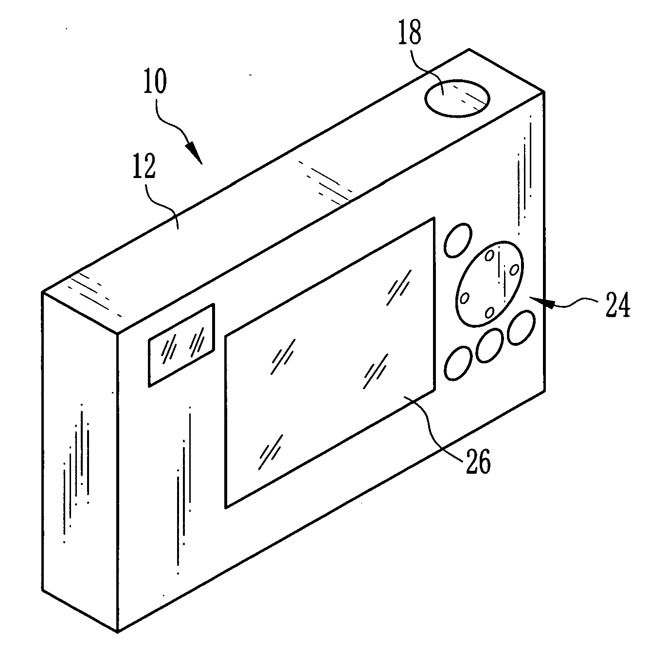
[0032] In FIG. 2, an operating section 24 and an LCD 26 are disposed on a rear surface of the camera body 12. The operating section 24 is composed of a mode selection button for selecting one of the image capture mode, a playback mode and a menu mode, a zoom button for v...


PUM


Abstract

First pixels and second pixels are arranged in an LCD of a digital camera. Image light from the first pixel is diffused by a diffusing filter. Image light from the second pixel is deflected by a prism and directed in an oblique direction. When the LCD is viewed from a forward direction, only a captured image generated by the first pixels is observed. When the LCD is viewed from the oblique direction, the captured image, and camera information generated by the second pixels are observed in a state that they overlap each other.

Description

BACKGROUND OF THE INVENTION [0001] 1. Field of the Invention [0002] The present invention relates to a digital camera which records captured images as digital image data. [0003] 2. Description Related to the Prior Art [0004] Digital cameras are well known, and record subject images as digital image data to a data storage. The digital cameras have a display device such as a liquid crystal display (LCD) for displaying various images. The display device displays a through image of a subject at the time of framing, and camera information such as remaining battery charge, number of available recording frames, a shooting condition and the like over the through image. When the camera information is displayed over the through image, part of the through image is replaced by the camera information, and therefore the thorough image cannot be viewed clearly and appropriately. [0005] Such problem can be solved by providing a sub display device in addition to a main display device, and displaying...

Claims


Application Information

Patent Timeline
IPC IPC(8): H04N5/222
CPCH04N5/23293H04N23/633
Inventor FUJIMURA, YUICHI
Owner FUJIFILM CORP
Learn More