Positioning hinge

a hinge and hinge body technology, applied in the field of positioning hinges, can solve the problems of conventional hinges being difficult to use, the cover may fall and strike the body, and the hinge may not be able to meet the needs of use,

Inactive Publication Date: 2007-07-12
SHIN ZU SHING
View PDF20 Cites 13 Cited by
  • Summary
  • Abstract
  • Description
  • Claims
  • Application Information

AI Technical Summary

Benefits of technology

[0009] The main objective of the present invention is to provide a positioning hinge that can strongly hold an object mounted on the hinge in a position.
[0010] The positioning hinge comprises a pintle, a leaf assembly and a positioning element. The pintle is mounted in the leaf assembly and connects to the positioning element. The leaf assembly has a surface to rub against the positioning element to generate a growing friction. With the pintle and the leaf assembly being mounted in a cover and a body respectively, the growing friction generated by the positioning element and the leaf assembly will make the hinge strongly hold the cover relative to the body and keep the cover from striking the body.

Problems solved by technology

Although conventional hinges mounted on a covered electronic device allow the cover to be raised, they normally have no capability to hold the cover in a desired position, which would probably causes the cover to drop and strike the body when the cover is raised.
Even if conventional hinges can position the cover, they only provide weak support that is inadequate to overcome the torque generated by the weight of the cover, and the cover may possibly strike the body.
The shortcomings addressed make conventional hinges difficult to use.

Method used


Image

  • Positioning hinge
  • Positioning hinge
  • Positioning hinge

Examples


first embodiment

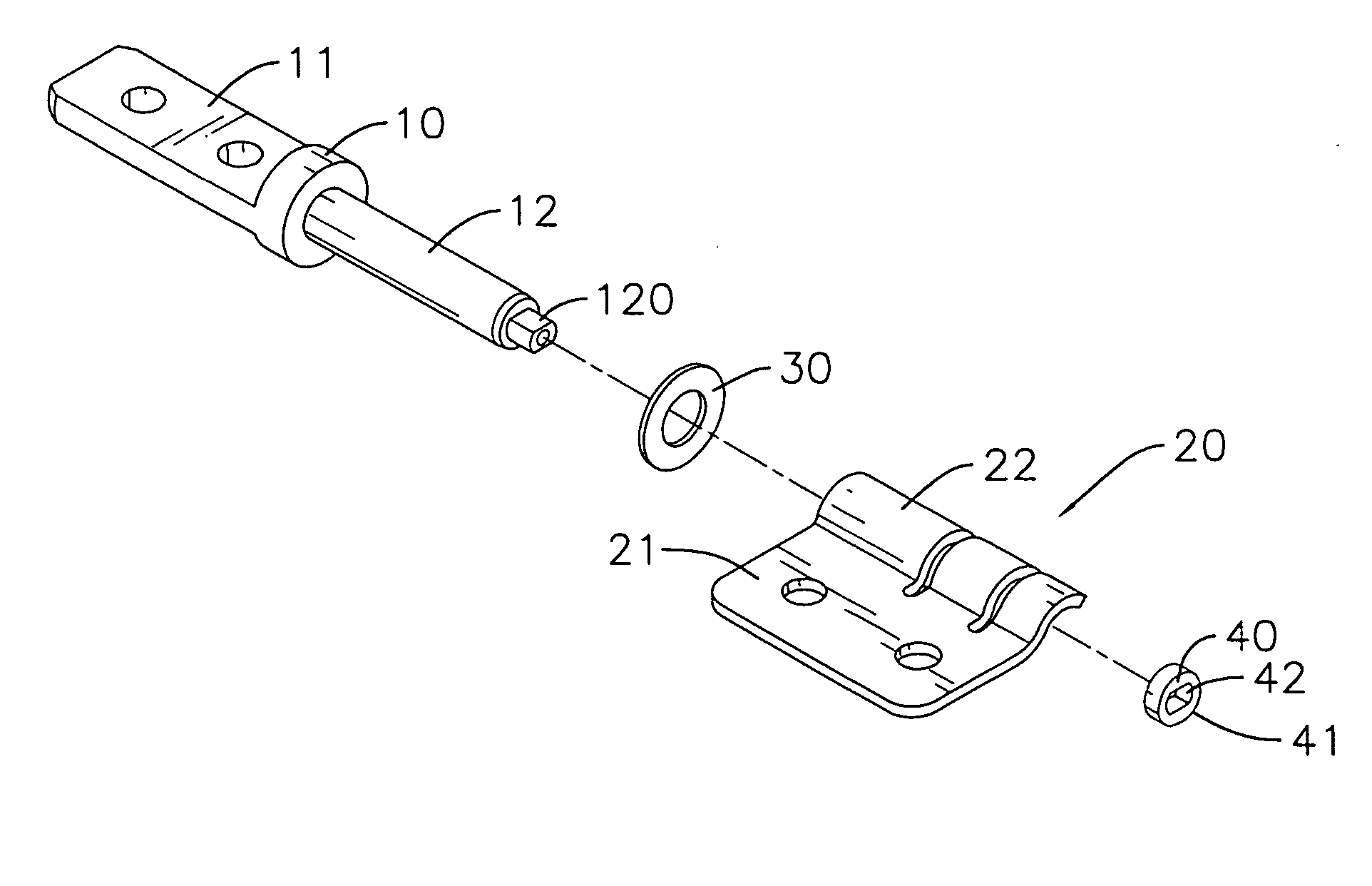
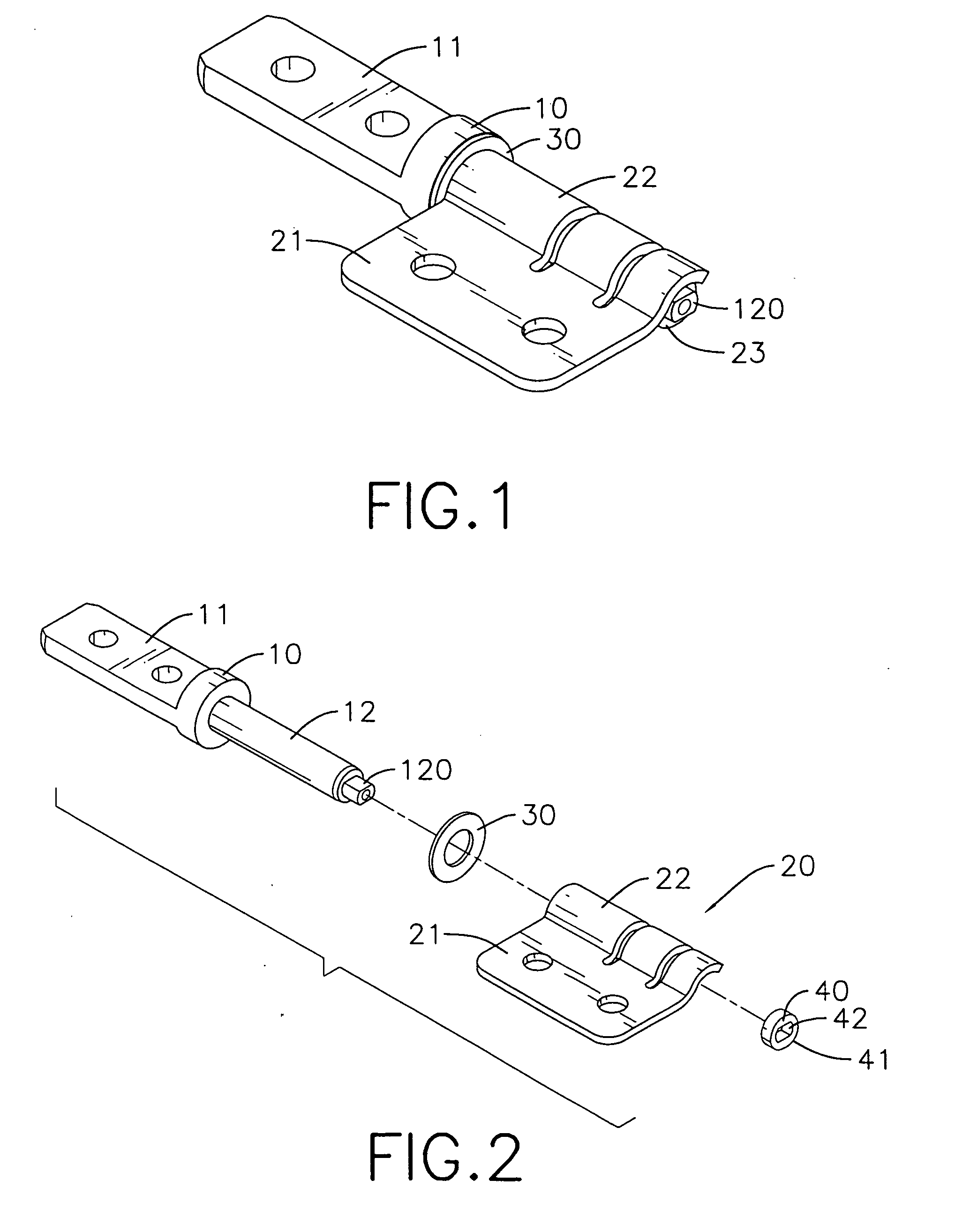
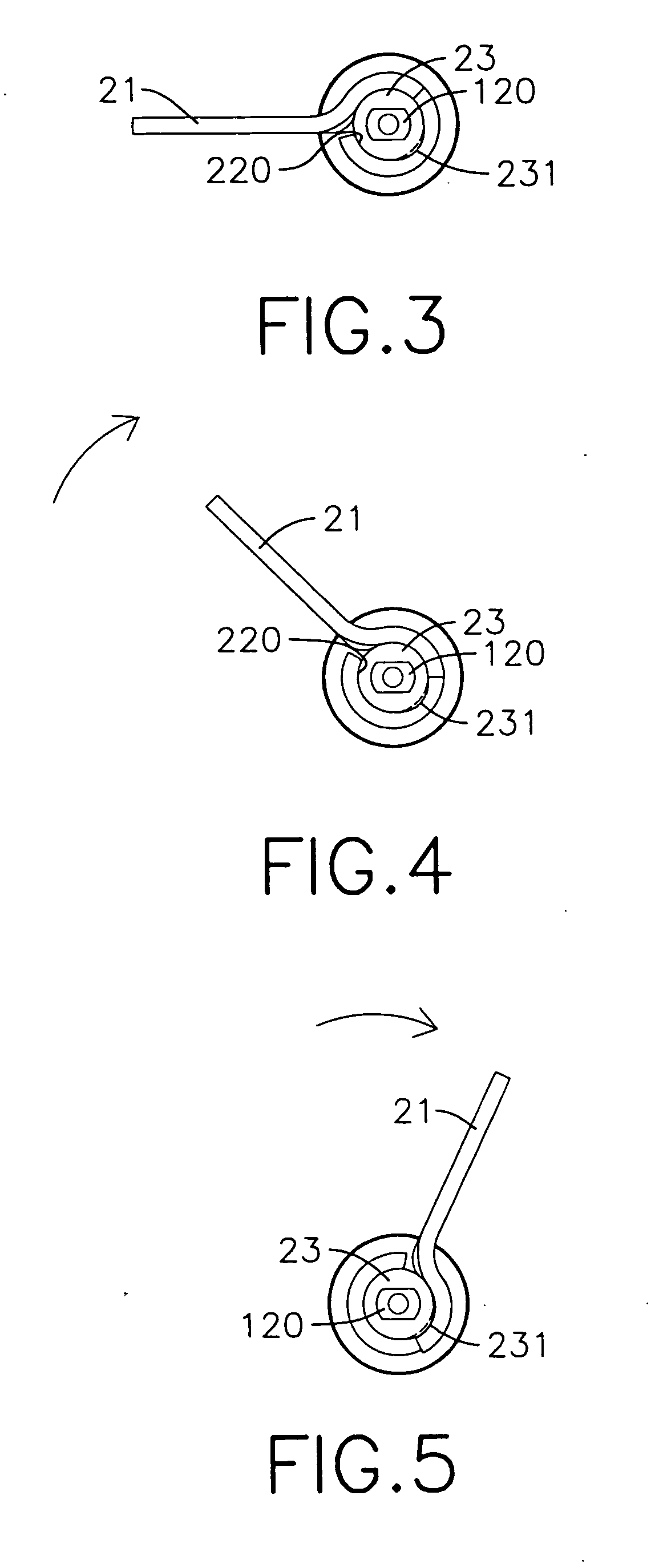
[0028] With reference to FIGS. 1, 2 and 3 to 5, the positioning hinge in the first embodiment comprises a leaf assembly (20), a pintle (10), an optional washer (30) and a cam (40) as positioning element.

[0029] The barrel (22) of the leaf assembly (20) is tubular and has a proximal end, a distal end, a longitudinal gap and an inner surface (220). The longitudinal gap is formed from the proximal end to the distal end and allows the barrel (22) to expand slightly. The inner surface (220) is formed inside the barrel (22).

[0030] The pintle (10) has a proximal end, a distal end, a connector (11) and a shaft (12). The connector (11) is defined on and protrudes longitudinally from the proximal end of the pintle (10) and can be mounted in a body (51) (with reference to FIG. 13). The shaft (12) is defined on the distal end, which extends through the washer (30) and mount into the barrel (22) of the leaf assembly (20) and has a distal end and a non-circular sectional axle (120) formed on the ...

second embodiment

[0032] With reference to FIGS. 6, 7 and 10 to 12, the positioning hinge in the second embodiment comprises a leaf assembly (20′), a pintle (10), an optional washer (30) and a rod (40′) as a positioning element. The leaf assembly (20′) has a leaf (21) and a barrel (22′). The barrel (22′) is tubular and has a middle, a cutout (224), a side end, two flanges (222)(223) and a sloping surface (221). The cutout (224) is defined on the middle and has two sectional surfaces. The sloping surface (221) is formed on the side end. The flanges (222)(223) are formed on the side end separately.

[0033] The pintle (10) has a proximal end, a distal end, a connector (11) and a shaft (12′). The connector (11) is defined on and protrudes longitudinally from the proximal end of the pintle (10) and can be mounted in a body (51) (with reference to FIG. 13). The shaft (12′) is defined on the other end, which passes through the washer (30) and mounts into the barrel (22′) of the leaf assembly (20′) and has a d...

third embodiment

[0035] With reference to FIG. 8, 9, in the third embodiment, the said sloping surface (221) and the flanges (222)(223) are formed on one sectional surfaces of the cutout (224), and the said mounting hole (121) is also formed on the middle of the shaft (12′). Such that the rod (40′) is located at the middle of the shaft (12′) and the head (42′) rubs against the sloping surface (221) to generate a growing friction and provide the same effect.

[0036] With reference to 10, 11 and 12, the rod (40′) is wedged by the flanges (222)(223) to limit the rotational angle of the cover (52).

[0037] With further reference to FIG. 13, when the cover (52) is raised, the first leaf (21) mounted in the cover (52) is turned round simultaneously. When the cover (52) is turned, the positioning element (40, 40′) rubs against the surface (220,221) consequentially and generates a growing friction. With the growing friction, the hinge in accordance to the present invention is then able to strongly hold the rai...


PUM


Abstract

The positioning hinge has a pintle, a leaf assembly and a positioning element. The pintle is mounted in the leaf assembly and is connected with the positioning element. The leaf assembly has a surface, and the positioning element rubs against the positioning element to generate a growing friction. When the pintle and the leaf assembly are mounted to a cover and a body respectively, the growing friction generated by the positioning element and the leaf assembly makes the cover to be positioned at a desired position relative to the body.

Description

BACKGROUND OF THE INVENTION [0001] 1. Field of the Invention [0002] The present invention relates to a positioning hinge, and more particular to a hinge used to strongly hold an object in a position. [0003] 2. Description of Related Art [0004] Hinges are widely used on covered electronic devices such as notebook computers or pocket game computers. The covered electronic devices often have a body and a cover. The cover often has a built-in monitor and is attached pivotally to the body by hinges to raise or lower. [0005] Although conventional hinges mounted on a covered electronic device allow the cover to be raised, they normally have no capability to hold the cover in a desired position, which would probably causes the cover to drop and strike the body when the cover is raised. [0006] Even if conventional hinges can position the cover, they only provide weak support that is inadequate to overcome the torque generated by the weight of the cover, and the cover may possibly strike the ...

Claims


Application Information

Patent Timeline
Patent Type & Authority Applications(United States)
IPC IPC(8): E05D11/08
CPCE05D11/06Y10T16/54038E05Y2900/606
Inventor LU, SHENG-NANCHIEN, HSIANG-CHI
Owner SHIN ZU SHING
Why Eureka
Try Eureka