Spindle Motor and Recording Disk Driving Apparatus Having the Spindle Motor

a spindle motor and recording disk technology, applied in the direction of structural association, dynamo-electric machines, instruments, etc., can solve the problems of static electricity, potential difference between the recording disk and the bracket, and breakage of the magnetic head, so as to secure the electrical conduction

Inactive Publication Date: 2006-09-28
NIDEC CORP
View PDF20 Cites 5 Cited by
  • Summary
  • Abstract
  • Description
  • Claims
  • Application Information

AI Technical Summary

Benefits of technology

[0014] This invention has been achieved in view of the problem described above, and the object thereof is to provide a spindle motor and a recording disk driving apparatus having the spindle motor in which the housing and the bracket can be fixed positively and accurately, while at the same time securing electrical conduction.

Problems solved by technology

The spindle motor used for the recording disk driving apparatus described above poses the problem of static electricity described below.
Specifically, once the spindle motor is driven and the recording disk is rotated at high speed, friction occurs between the recording disk and the air, with the result that the recording disk is charged by static electricity, thereby causing a potential difference between the recording disk and the bracket.
This in turn generates a potential difference between the recording disk and the magnetic head, and electric discharge is caused between the recording disk and the magnetic head, thereby often breaking the magnetic head.
Without some preventive structure against the potential difference, therefore, breakage may result.
Depending on the temperature of the operating environment, therefore, the bonded joint may develop an excessive thermal stress causing a cracking or separation.
Unless a sufficient amount of the conductive adhesive is coated between the housing and the bracket, therefore, the vibration stress and the thermal stress, etc. due to the temperature of the operating environment causes the cracking or separation of the conductive adhesive, which may be aggravated gradually.
Once this phenomenon occurs in the conductive adhesive, the electrical conduction between the housing and the bracket is adversely affected.
Also, many conductive adhesives use silver as a main component and therefore, are high in price.
An excessively small amount of the conductive adhesive, however, would adversely affect the conduction between the housing and the bracket.

Method used


Image

  • Spindle Motor and Recording Disk Driving Apparatus Having the Spindle Motor
  • Spindle Motor and Recording Disk Driving Apparatus Having the Spindle Motor
  • Spindle Motor and Recording Disk Driving Apparatus Having the Spindle Motor

Examples


first embodiment

Structure of Spindle Motor

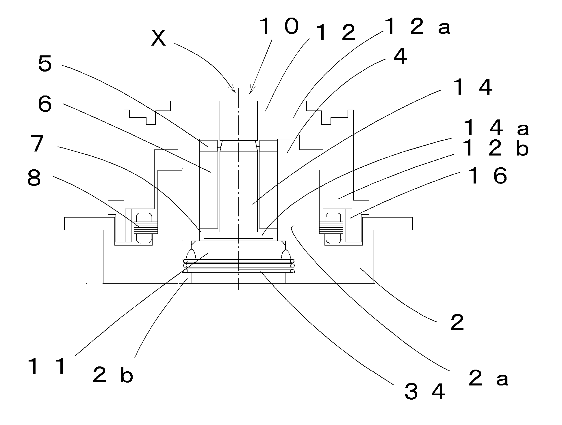
[0027] The first embodiment of the invention is explained with reference to FIG. 1. FIG. 1 is a longitudinal sectional view of the spindle motor used with, for example, a hard disk driving apparatus. This spindle motor includes a substantially cup-shaped bracket 2, a housing 4 inserted in a circular through hole 2a at the central portion of the bracket 2 and a sleeve 6 fitted on the inner peripheral surface of the housing 4.

[0028] The housing 4 is a hollow cylindrical member and constitutes an integrated structure by coupling a closing plate 11 by laser welding to the lower end of the housing 4. By seal welding the closing plate 11, oil 7 in the housing 4 can be held not to leak out. The inner peripheral surface of the sleeve 6 is in opposed relation to a rotor 10 in radial direction with a minuscule gap therebetween. The lower end surface of the sleeve 6 is in axially opposed relation to the upper surface of a shaft flange 14a arranged at the lower end ...

second embodiment

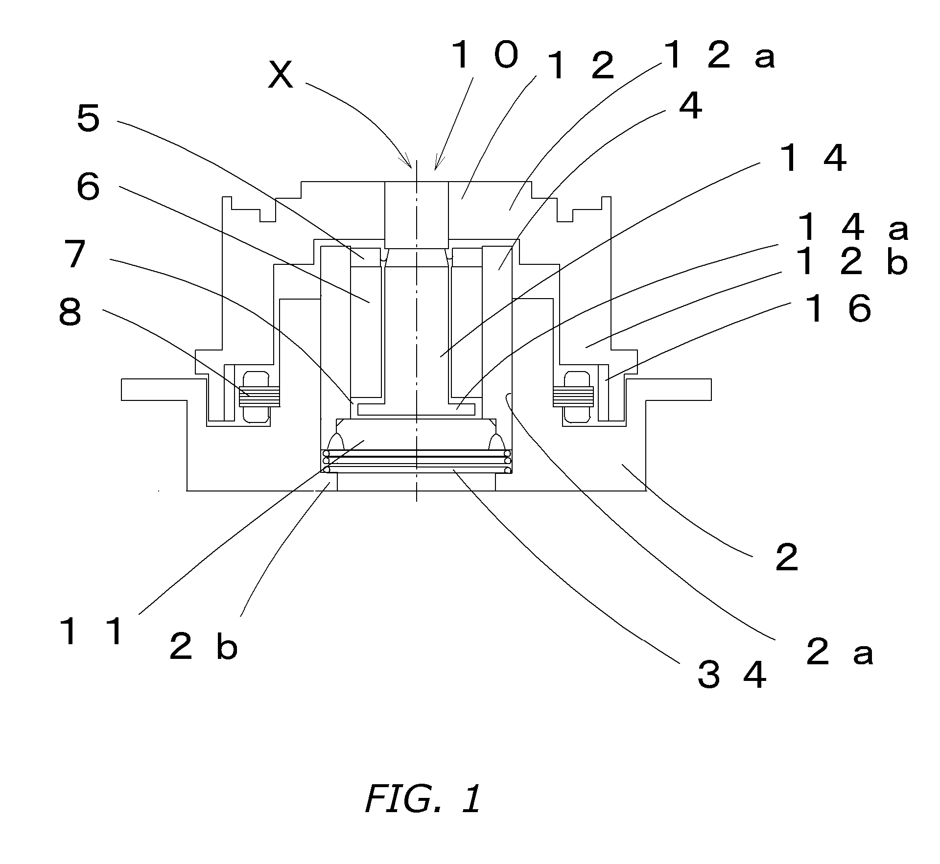
[0045] Next, a second embodiment of the invention is explained with reference to FIG. 2. The motor according to this embodiment has a basic structure equivalent to that of the first embodiment described above. Therefore, showing clearly the correspondence of reference numerals between corresponding component members in the order of 100, only different portions are explained.

[0046] A housing 104 is fixed in a circular through hole 102 at the central portion of a bracket 102 of the spindle motor shown in FIG. 2. The housing 104 is a substantially cup-shaped bottomed cylindrical member molded by conductive resin, and includes a housing flange 104a constituting a protrusion, on the outer periphery of an opening side, having a larger outer diameter than the inner diameter of the insertion portion of a circular through hole 102a. A sleeve 106 is fixed on the inner peripheral surface of the housing 104. The sleeve 106 is a porous sintered member impregnated with an oil 107. The material o...

third embodiment

[0052] Next, a third embodiment of the invention is explained with reference to FIG. 3. The motor according to this embodiment has the same basic structure as that of the second embodiment described above, and therefore, showing the correspondence of reference numerals between corresponding component members in the order of 200, only different portions are explained.

[0053] According to this embodiment, a conductive member 234 arranged between an upper end surface 202c of the bracket constituting the upper end of a circular through hole 202a and a housing flange 204a protruded outward of a housing 204 is in the shape of disk spring. The conductive member, however, is not limited to this shape and any members having a predetermined strength, rigidity and conductivity in the shape of peripherally corrugated spring or annular member having the cross section in the shape of “O”, “C” or “U”, for example, may be employed with equal effect.

[0054] The third embodiment can produce the simil...


PUM

PropertyMeasurementUnit
temperatureaaaaaaaaaa
elastic stressaaaaaaaaaa
shapeaaaaaaaaaa

Abstract

Spindle motor capable of positively fixing and securing conduction between a housing and a bracket, and a recording disk driving apparatus using the spindle motor. The bracket has a circular through hole, and the housing is fixedly inserted in the circular through hole. A protrusion is formed on at least one of the bracket and the housing. A conductive member is between and in contact with a flange and the bracket or the housing in the direction of the rotary axis to electrically connect the flange and the bracket or the housing. The conductive member is in contact with the flange and the bracket or the housing under an elastic stress.

Description

BACKGROUND OF THE INVENTION [0001] 1. Technical Field [0002] This invention relates to a spindle motor having the conduction function and a recording disk driving apparatus having the spindle motor. [0003] 2. Description of the Related Art [0004] With the recent increase in the recording density and improvement of the performance of the information storage device, the recording disk driving apparatus has been more and more reduced in size and increased more and more in rotational speed, while the field of application has widened even to the operation in an adverse environment under harsh temperature conditions. [0005] The spindle motor for rotationally driving the recording disk such a magnetic disk includes a rotor assembly having a shaft and a stationary assembly with a sleeve fixed thereon. The shaft is arranged on the inner periphery of the sleeve, and a rotor hub for mounting the recording disk is fixed at the upper end of the shaft. The sleeve is fixed on the inner periphery o...

Claims


Application Information

Patent Timeline
Patent Type & Authority Applications(United States)
IPC IPC(8): G11B17/02
CPCG11B19/2018H02K5/1675H02K11/0089H02K11/40
Inventor SUMI, SHIGEHARUOHIRO, TAKESHI
Owner NIDEC CORP
Why Eureka
Try Eureka