Compact hydraulic actuator system

a hydraulic actuator and compact technology, applied in the field of hydraulic systems, can solve problems such as system compactness

Inactive Publication Date: 2007-07-12
STRATTEC POWER ACCESS
View PDF9 Cites 54 Cited by
  • Summary
  • Abstract
  • Description
  • Claims
  • Application Information

AI Technical Summary

Benefits of technology

[0010]In one exemplary embodiment, a hydraulic actuator is disclosed, the hydraulic actuator comprising: a housing; a rod secured to a piston, the rod and piston being slidably received within the housing, wherein the rod along with the piston is capable of movement between a first position and a second position; a first chamber positioned on one side of the piston and within the housing; a second chamber positioned on another side of the piston and within the housing; a self contained flexible volume compensator disposed within the housing; a fluid disposed in the first chamber, the second chamber and the self contained flexible volume compensator, wherein the fluid in the self contained flexible volume compensator is pressurized to a predetermined pressure level; a bidirectional pump for moving the fluid between the first chamber, the second chamber and the self contained flexible volume compensator; a valve system disposed in the housing and for providing selective fluid communication between the first chamber, the second chamber and the self contained flexible volume compensator as the rod moves in a range of movement defined by the first position and the second position, wherein the valve system isolates the first chamber from the self contained flexible volume compensator and the second chamber when a fluid pressure in at least one of the first chamber, the second chamber and the self contained flexible volume compensator is below a predetermined level; and wherein the pressurized fluid in the self contained flexible volume compensator is transferred from the self contained flexible volume compensator to the second chamber via the pump and fluid in the first chamber is transferred to pump from the first chamber when the rod is moved toward the second position and wherein fluid in the second chamber is transferred from second chamber to the self contained flexible volume compensator and the first chamber when the rod and piston are moved towards the first position.
[0011]In another exemplary embodiment, a method for actuating a rod of a hydraulic actuator is provided the method comprising: pressurizing a fluid in a self contained flexible volume compensator of the hydraulic actuator; and displacing a portion of the fluid of the self contained flexible volume compensator into a second chamber of the hydraulic actuator as a rod of the hydraulic actuator moves from a first position towards a second position wherein a piston coupled to the rod increases a volume of the second chamber and decreases a volume of a first chamber, wherein a portion of a fluid in the second chamber is transferred to the self contained flexible volume compensator when the rod moves from the second position to the first position, and wherein the self contained flexible volume compensator, the first chamber and the second chamber are disposed within a housing of the hydraulic actuator and a valve system disposed in the housing provides selective fluid communication between the first chamber, the second chamber and the self contained flexible volume compensator as the rod moves in a range of movement defined by the first position and the second position, wherein the valve system isolates the first chamber from the self containe

Problems solved by technology

Accordingly, some disadvantages of these hydraulic actuators are that the system is not compact, connecting pipes are required and provide po

Method used


Image

  • Compact hydraulic actuator system
  • Compact hydraulic actuator system
  • Compact hydraulic actuator system

Examples


Embodiment Construction

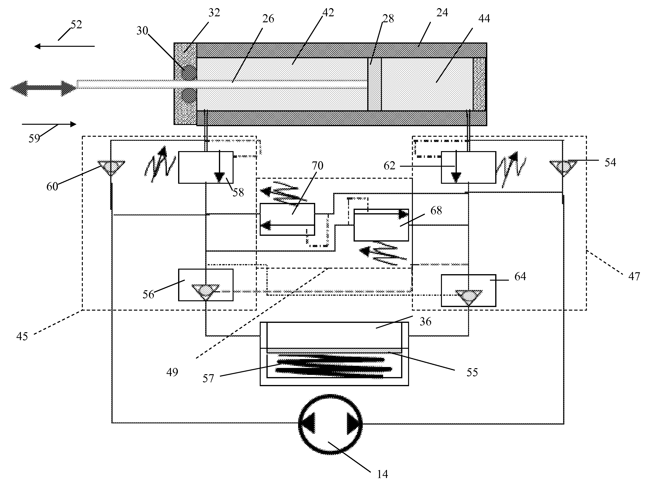
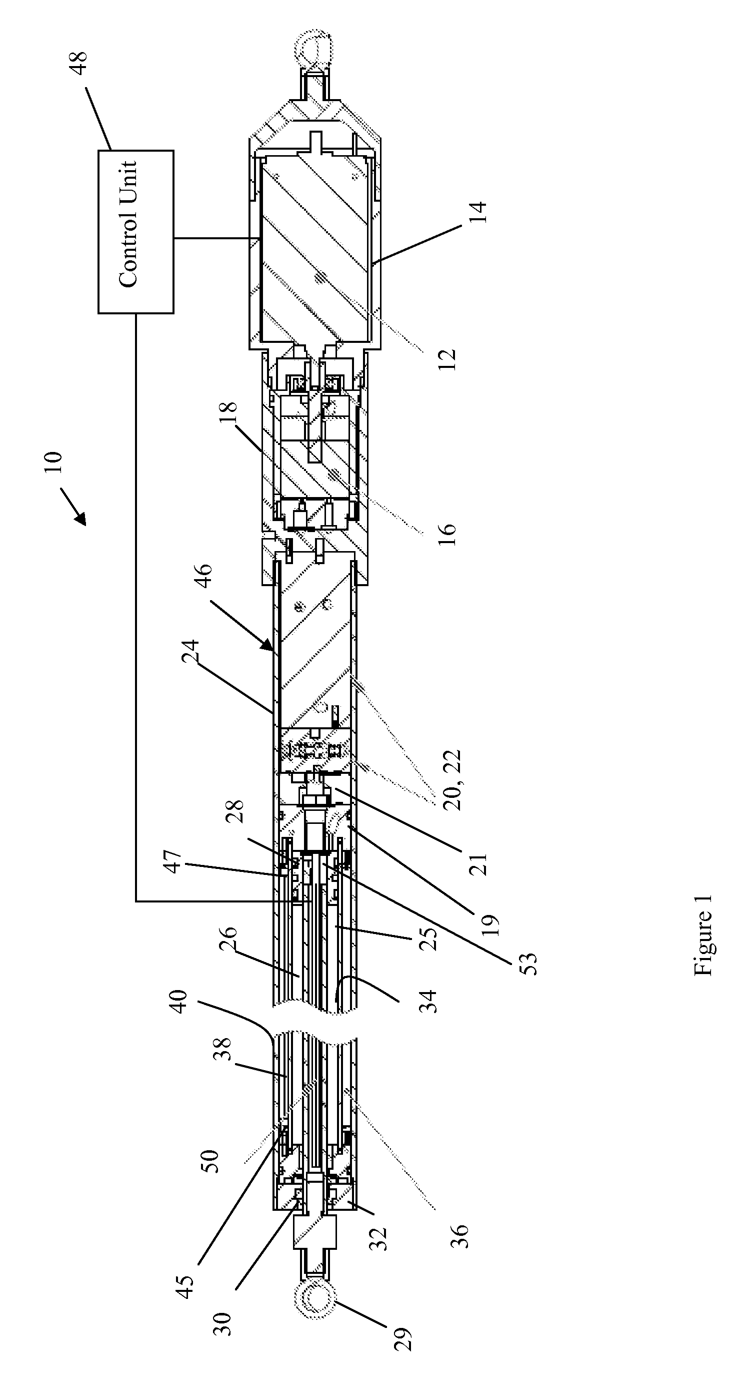
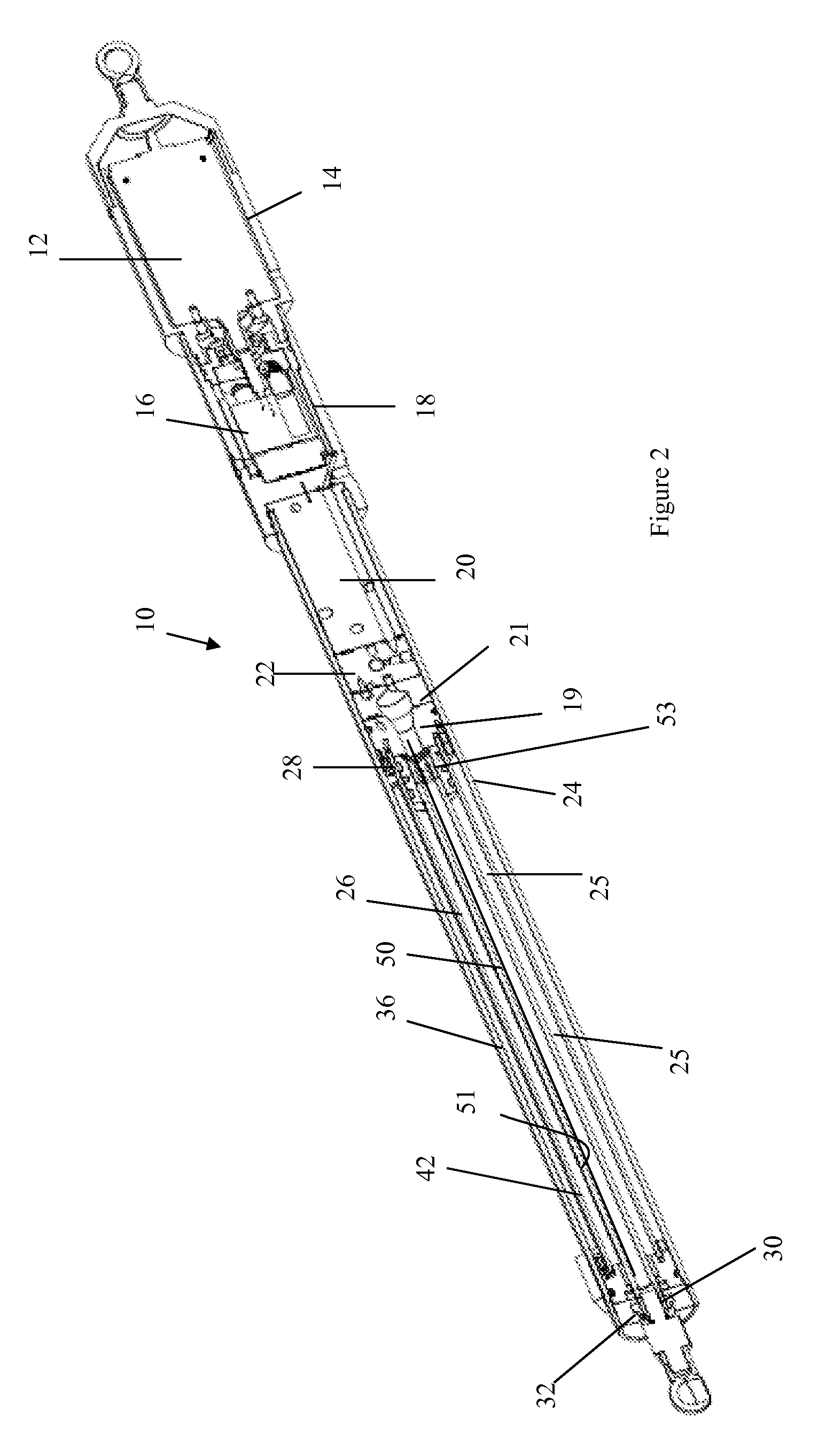
[0024]Exemplary embodiments of the present invention relate to an integrated, self-contained, compact in-line hydraulic system. In one exemplary embodiment, the modular compact in-line hydraulic system is used as an actuator for automotive applications, such as driving a side door, tail gate, sliding door, deck lit, etc. In another exemplary embodiment, the modular compact in-line hydraulic system can also be used as a driving device for many other industrial fields where a compact in-line actuator system is desired, such as medical machines, health and sport training machines, assembly stations or lines, testing machines, lifting or actuating units in aerospace industries, etc.

[0025]Referring now to FIGS. 1-3 a hydraulic actuator 10 in accordance with an exemplary embodiment of the present invention is illustrated. In accordance with an exemplary embodiment of the present invention, hydraulic actuator 10 comprises an integrated, self contained, compact in-line hydraulic system. Hyd...


PUM


Abstract

A hydraulic actuator, comprising: a housing; a rod secured to a piston, the rod and piston being slidably received within the housing, wherein the rod along with the piston is capable of movement between a first position and a second position; a first chamber positioned on one side of the piston and within the housing; a second chamber positioned on another side of the piston and within the housing; a self contained flexible volume compensator disposed within the housing; a fluid disposed in the first chamber, the second chamber and the self contained flexible volume compensator, wherein the fluid in the self contained flexible volume compensator is pressurized to a predetermined pressure level; a bidirectional pump for moving the fluid between the first chamber, the second chamber and the self contained flexible volume compensator; a valve system disposed in the housing and for providing selective fluid communication between the first chamber, the second chamber and the self contained flexible volume compensator as the rod moves in a range of movement defined by the first position and the second position, wherein the valve system isolates the first chamber from the self contained flexible volume compensator and the second chamber when a fluid pressure in at least one of the first chamber, the second chamber and the self contained flexible volume compensator is below a predetermined level; and wherein the pressurized fluid in the self contained flexible volume compensator is transferred from the self contained flexible volume compensator to the second chamber via the pump and fluid in the first chamber is transferred to pump from the first chamber when the rod is moved toward the second position and wherein fluid in the second chamber is transferred from second chamber to the self contained flexible volume compensator and the first chamber when the rod and piston are moved towards the first position.

Description

CROSS REFERENCE TO RELATED APPLICATIONS[0001]This application is related to U.S. Provisional Patent Application Ser. No. 60 / 757,663 filed Jan. 10, 2006, the contents of which are incorporated herein by reference thereto.BACKGROUND[0002]Exemplary embodiments of the present invention relate to a hydraulic system. More particularly, exemplary embodiments of the present invention relate to an apparatus and method for providing a compact hydraulic system.[0003]Hydraulic actuators are commonly found in many engineered systems for a wide range of applications, including military, space, aerospace, and many industrial applications. Generally, a hydraulic system includes some elements such as a pump, a fluid supplier (reservoir), a connecting piping system, a closed hydraulic cylinder, and necessary control valves, etc. An electrical motor is commonly used to drive the hydraulic pump to pressurize the fluid for function. Traditionally, those elements of the hydraulic system are designed as s...

Claims


Application Information

Patent Timeline
IPC IPC(8): F16D31/02
CPCF15B1/02F15B1/265F15B15/18F15B2211/20561F15B2211/7053F15B2211/3051F15B2211/50527F15B2211/625F15B2211/212
Inventor HE, XINHUA
Owner STRATTEC POWER ACCESS
Why Eureka
Try Eureka