
Backlight unit improved in light mixing feature

Active Publication Date: 2007-07-12
SAMSUNG ELECTRONICS CO LTD
View PDF7 Cites 14 Cited by
  • Summary
  • Abstract
  • Description
  • Claims
  • Application Information

AI Technical Summary

Benefits of technology

[0020] The present invention has been made to solve the foregoing problems of the prior art and therefore an aspect of the present invention is to provide a backlight unit improved in light mixing feature, in which light beams outputted from optical devices are effectively dispersed and mixed together, thereby achieving uniform white light free from color stains.
[0021] Another aspect of the invention is to provide a backlight unit improved in light mixing feature, which produces uniform white light without color stains to thereby elevate quality of finished products remarkably and enhance product competitiveness.

Problems solved by technology

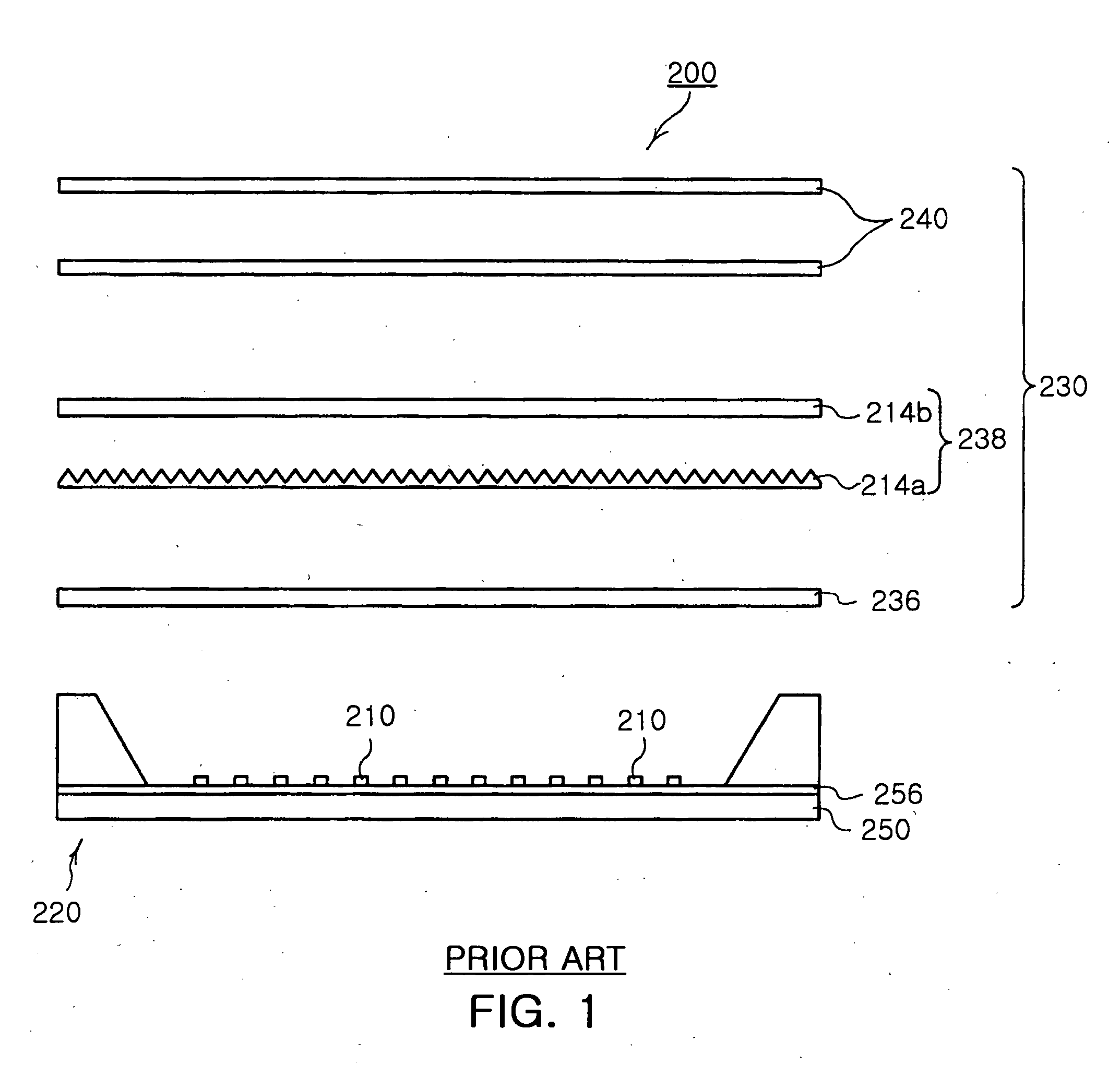
The CCFL, which uses a mercury gas, may trigger environmental pollution.
Besides, the CCFL has low response rate, low color reproducibility, and inappropriateness for a lighter and smaller LCD panel.
This resultantly causes color stains.
Accordingly, the surface light source 220 of the conventional LCD backlight fails to output uniform white light due to color stains.

Method used


Image

  • Backlight unit improved in light mixing feature
  • Backlight unit improved in light mixing feature
  • Backlight unit improved in light mixing feature

Examples


Embodiment Construction

[0037] Exemplary embodiments of the present invention will now be described in detail with reference to the accompanying drawings.

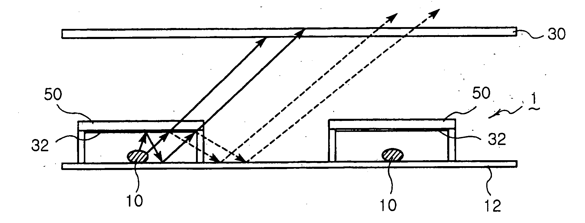
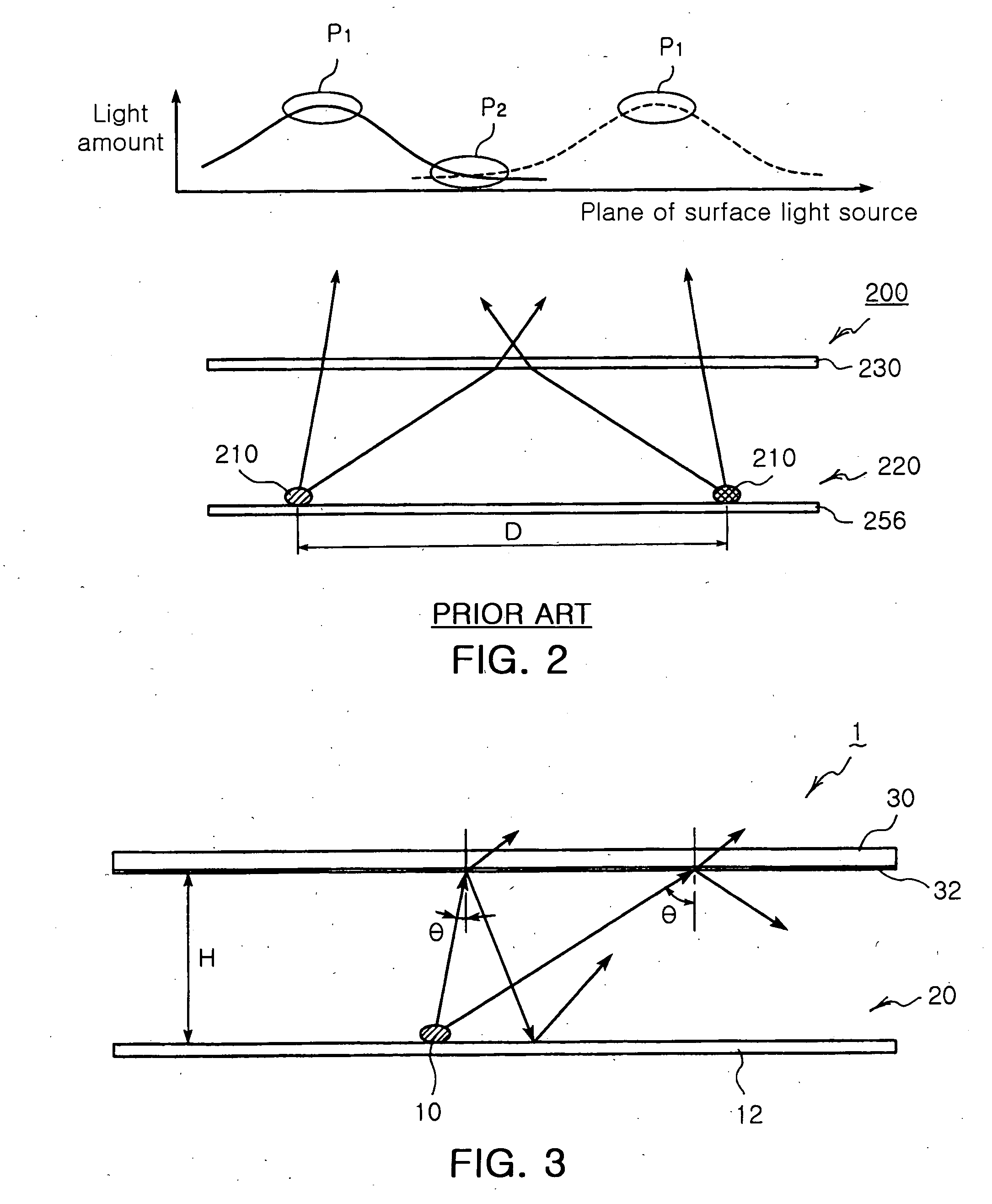
[0038] As shown in FIG. 3, a backlight unit 1 improved in light mixing feature according to the invention includes a surface light source 12 having a reflecting surface 12 with a plurality of optical devices 10 mounted thereon.

[0039] The surface light source 20 has the reflecting surface 12 formed on the rear side thereof opposite to the front side where the optical devices 10 are mounted. The reflecting surface 12 reflects light beams outputted from the optical device 10 in a forward direction.

[0040] Here, the optical devices 10 are exemplified by not only LED devices but also devices such as lamps.

[0041] The backlight unit 1 improved in light mixing feature according to the invention includes an optical sheet 30 disposed in front of the surface light source 20. The optical sheet 30 is preferably made of Poly Methylmethacrylate (PMMA), and the reflec...


PUM


Abstract

Light beams are outputted from optical devices and mixed together to obtain uniform white light free from color stains, thereby achieving a backlight unit improved in light mixing feature. In the backlight unit, a surface light source has a reflecting surface with a plurality of optical devices mounted thereon. An optical sheet is disposed in front of the surface light source. A reflecting layer is disposed between the surface light source and the optical sheet and has reflectivity varied by an incident angle of light beams from the optical devices. The backlight unit enables the light beams from the optical devices to be mixed together. The light beams outputted from the optical devices are effectively mixed together by a reflecting layer having reflectively varied by an incident angle of the light beams from the optical devices, thereby achieving uniform white light without color stains.

Description

CLAIM OF PRIORITY [0001] This application claims the benefit of Korean Patent Application No. 2006-03129 filed on Jan. 11, 2006 in the Korean Intellectual Property Office, the disclosure of which is incorporated herein by reference. BACKGROUND OF THE INVENTION [0002] 1. Field of the Invention [0003] The present invention relates to a liquid crystal display (LCD) backlight unit employing a plurality of optical devices, and more particularly, to a backlight unit improved in light mixing feature, in which light beams outputted from the optical devices are effectively dispersed and mixed together, thereby producing uniform white light free from color blur. [0004] 2. Description of the Related Art [0005] A Cold Cathode Fluorescent Lamp (CCFL) has been adopted for a light source of a conventional Liquid Crystal Display (LCD) backlight. The CCFL, which uses a mercury gas, may trigger environmental pollution. Besides, the CCFL has low response rate, low color reproducibility, and inappropri...

Claims


Application Information

Patent Timeline
IPC IPC(8): G02F1/1335
CPCG02F1/133603G02F1/133609G02F1/133606G02F1/133605G08G1/123
Inventor LEE, HYUN HOYUN, HYEONG WON
Owner SAMSUNG ELECTRONICS CO LTD
Learn More