
Lancet device

a technology of a needle hub and a ring, which is applied in the field of needle hubs, can solve the problems that another person may be infected by the needle hub used, and achieve the effect of preventing the infected person from being infected by the needle hub

Inactive Publication Date: 2007-07-12
LI FU YUAN
View PDF4 Cites 110 Cited by
  • Summary
  • Abstract
  • Description
  • Claims
  • Application Information

AI Technical Summary

Benefits of technology

[0005] The objective of the present invention is to provide a lancet device that can be used a needle once to protect a next person who is pricked his skin by the used needle.

Problems solved by technology

However, a used needle hub maybe reused again due to a user's carelessness, so another person may be infected by the used needle hub.

Method used


Image

  • Lancet device
  • Lancet device
  • Lancet device

Examples


Embodiment Construction

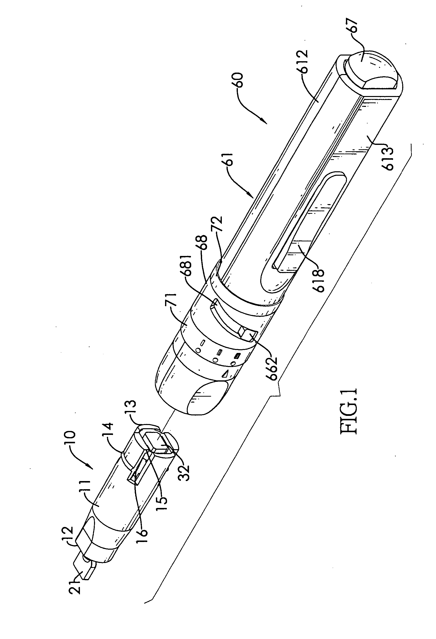
[0017] With reference to FIG. 1, a lancet device in accordance with the present invention comprises a needle assembly (10) and a lancet carrier (60).

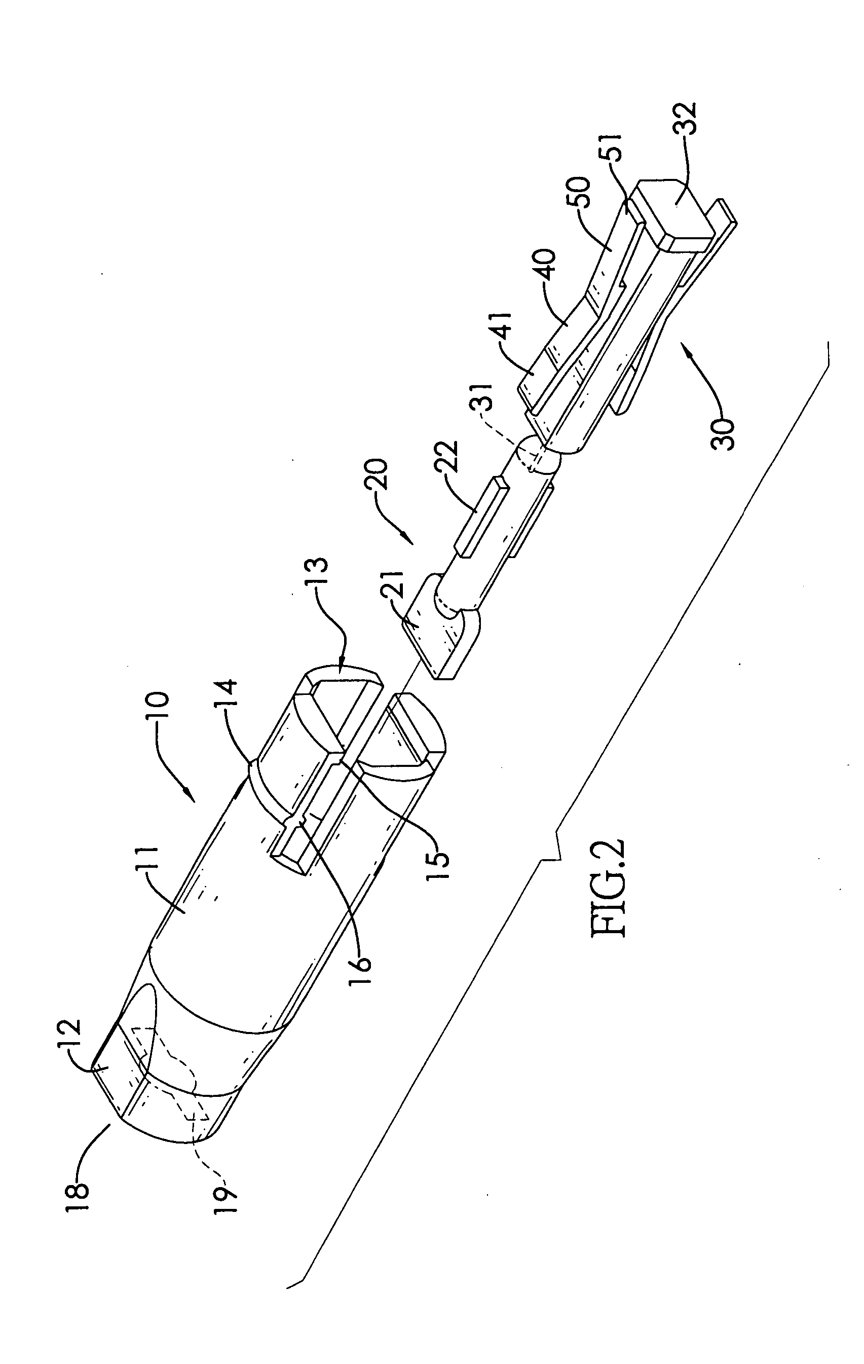
[0018] With further reference to FIGS. 2 to 4, the needle assembly (10) comprises a casing (11), a needle hub (30), a retracting unit (40), a limit unit (50) and an optional needle cap (20).

[0019] The casing (11) is cylindrical and hollow and comprises an axle, an outer surface, an inner surface, a front end (12), a rear end (13), a rear stop (15), a front stop (16), a neck (17), an opening (18), multiple optional circumference protrusions (14) and two optional lateral notches (19). The rear stop (15) is formed on the inner surface of the casing (10) near the rear end (13). The front stop (16) is formed on the inner surface of the casing (10) between the rear end (13) and the front end (12). The neck (17) is formed on the casing (10) near the front end (12). The opening (18) is formed through the front end (12) and is optionally circu...


PUM


Abstract

A lancet device has a needle assembly and a needle carrier. The needle assembly has a casing, a needle hub, a retracting unit and a limit unit. The needle hub with a needle is mounted in the casing. The retracting unit and the limit unit connect to the needle hub to limit the needle hub to move. The lancet carrier has a housing, a pushing rod, a spring and a cap. The housing connects the needle assembly and has a pressing unit. The pushing rod is mounted in the housing and abuts with the needle hub after pushing the pressing unit to release the force of the spring so the needle protrudes from the needle assembly. After pressing the cap, the needle assembly releases from the needle carrier. Therefore, the new needle assembly can be mounted in the lancet carrier to prick again.

Description

BACKGROUND OF THE INVENTION [0001] 1. Field of the Invention [0002] The present invention relates to a lancet device, and especially to a lancet device for obtaining small amount blood conveniently. [0003] 2. Description of the Related Art [0004] A conventional lancet device comprises a casing and a needle hub. The casing comprises a connector and a driver assembly. The connector and the driver assembly are mounted in the casing. The needle hub is mounted in the casing and comprises a needle. The needle hub is connected with the casing by the connector. The driver assembly is attached on the needle hub. When pushing the driver assembly, the needle is protruded from the needle hub and pricks into the skin of a person. Then, the needle is retracted into the needle hub to suck some blood into the casing through the needle. The driver assembly dose not return to the original position until the used needle hub is replaced with a new needle hub. However, a used needle hub maybe reused aga...

Claims


Application Information

Patent Timeline
Patent Type & Authority Applications(United States)
IPC IPC(8): A61M5/00
CPCA61B5/15142A61B5/1411A61B5/150022A61B5/15019A61B5/150412A61B5/150519A61B5/150549A61B5/150618A61B5/150717A61B5/150916A61B5/15113A61B5/15117A61B5/1519A61B5/15194
Inventor CHEN, YEN-HUILI, FU-YUANCHEN, TZER-MING
Owner LI FU YUAN
Learn More