Surgical clip

a surgical clip and clip technology, applied in the field of surgical clips, can solve the problems of crude application mechanism, and achieve the effect of improving the occlusive

Inactive Publication Date: 2007-07-12
WILD
View PDF39 Cites 118 Cited by
  • Summary
  • Abstract
  • Description
  • Claims
  • Application Information

AI Technical Summary

Benefits of technology

[0006] It is found that there is still room for improvement of the occlusive effect of the prior art clips.

Problems solved by technology

The clip has no inherent self closing bias, and the application mechanism is crude in that each clip must be loaded manually and individually on the applicator, in the open condition.
Again, this clip suffers from the disadvantages that each clip must be loaded manually and individually on the applier, in the open condition, and, to actuate the loaded applier, a surgeon must make available his whole dominant hand, because of the pliers-grip hand action required.

Method used


Image

  • Surgical clip
  • Surgical clip
  • Surgical clip

Examples


Embodiment Construction

Exemplified Features of the Clip

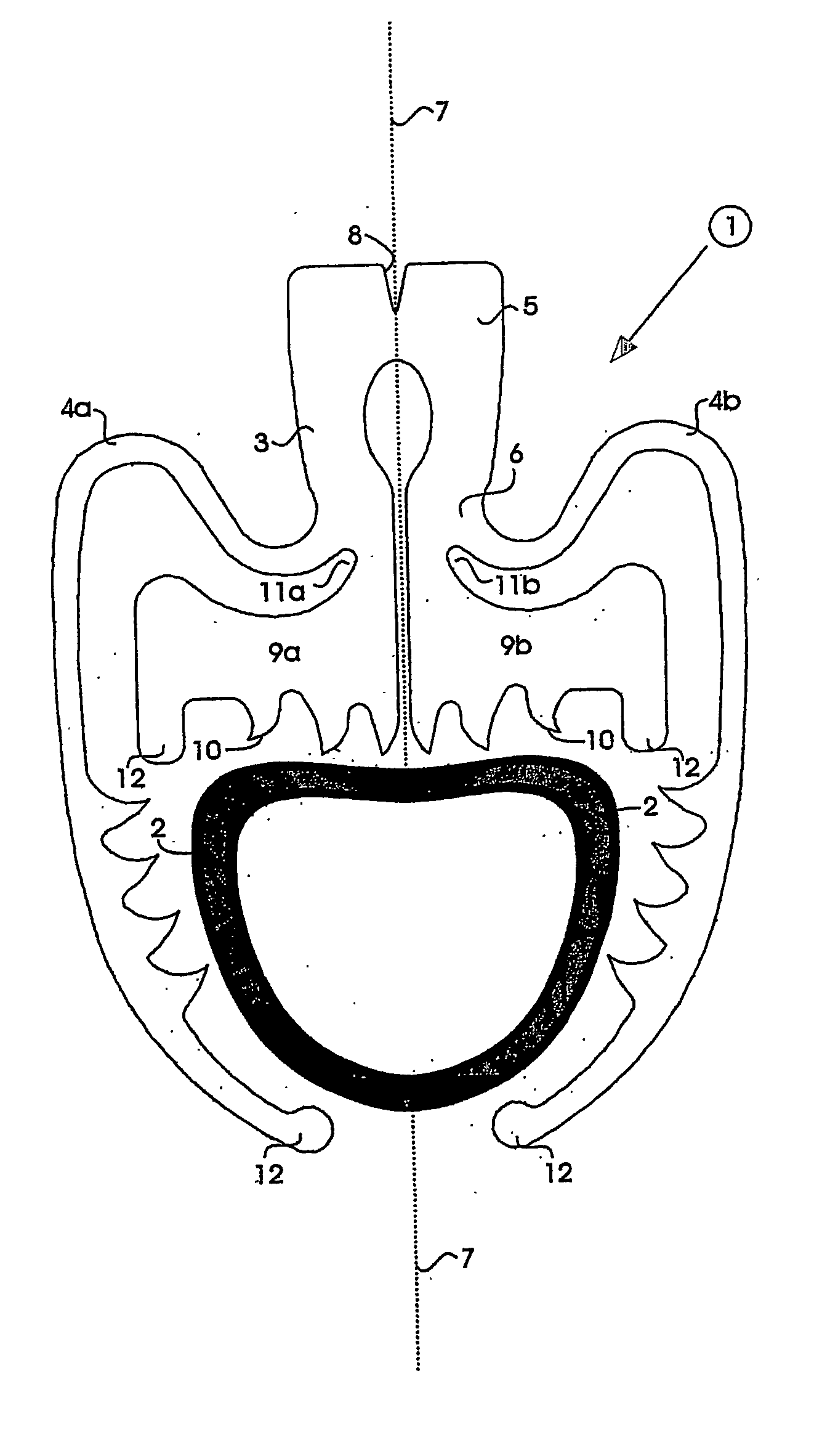
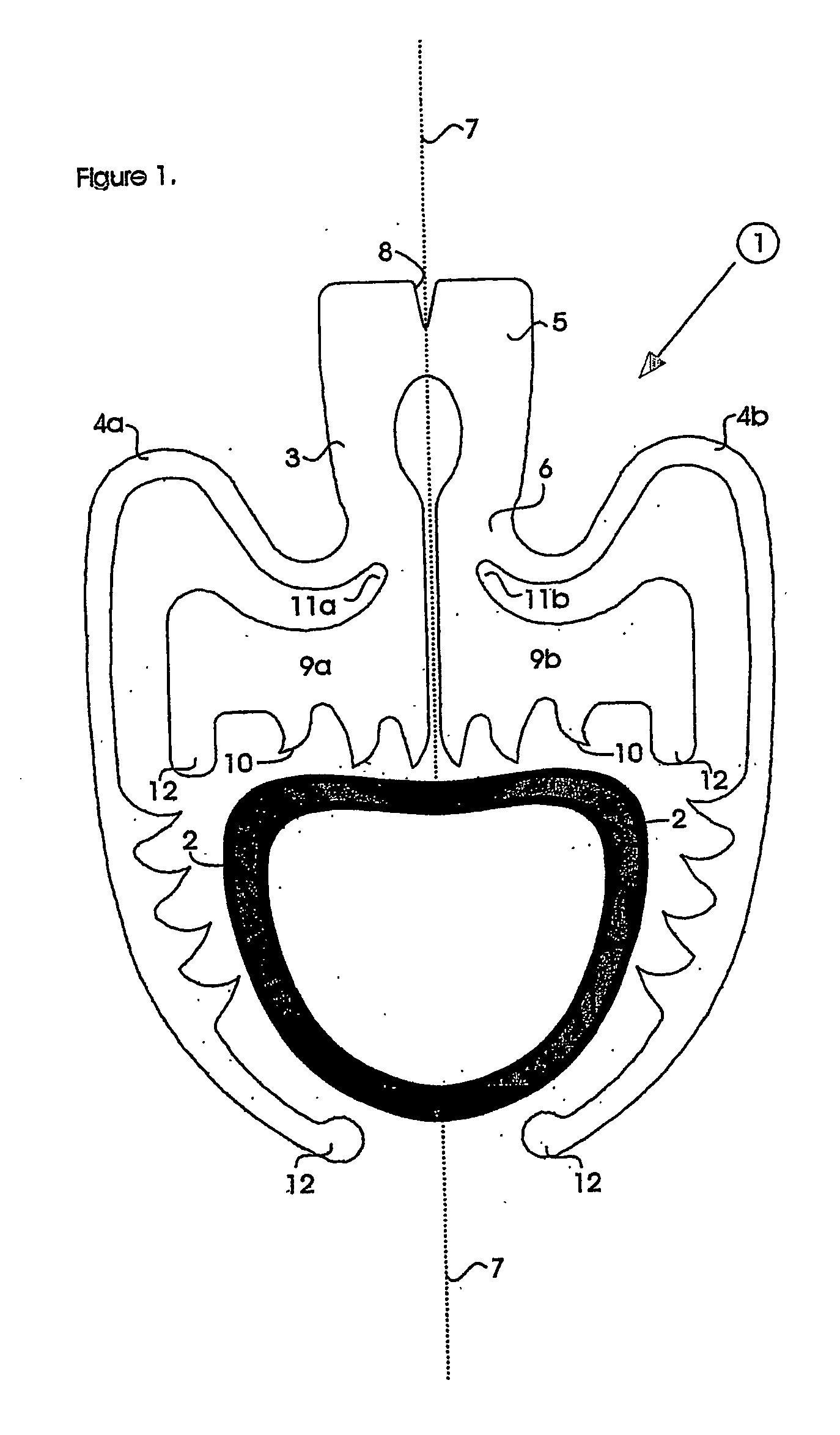
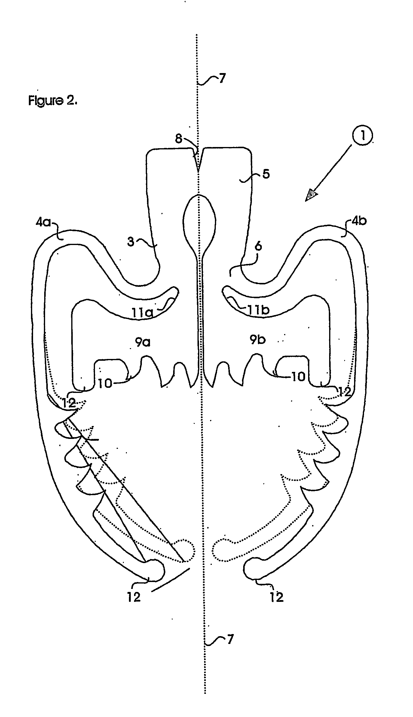
[0012] Preferably, the limb or limbs of the clip extend generally laterally outwardly from the base portion of the clip. Most preferably, the clip has a pair of such limbs each extending in opposite lateral directions from the base portion of the clip. The base and reaction portions are preferably disposed generally centrally between the pair of limbs.

[0013] The reaction surface is preferably substantially fixed in relation to the movement of the limb or limbs. The reaction surface is preferably elongate. The reaction surface may be straight or curved, and preferably has the form of a ridge or edge. The reaction surface and the limb or limbs are suitably dimensioned and arranged so that in the closed condition of the clip substantially the entire transverse width of the occluded body passageway is in contact with the reaction surface.

[0014] The clip is preferably generally planar, but the respective planes of the parts may be offset against one an...


PUM


Abstract

A surgical clip for occluding a vein, artery or other body passageway (2) comprises a base portion (3), a pair of resilient limbs (4a, 4b) configured to extend generally laterally outwardly from the base portion and each having a free end disposed forward of the base portion, and a reaction portion (9a/b) mounted to the base portion (3), the reaction portion defining a generally forwardly directed reaction surface (10) disposed between the base portion (3) and the free ends of the limbs (4a, 4b), the being movable under a resilient restoring force from a first, open, condition, in which a gap is provided between the limbs and the reaction portion for receiving the body passageway into the clip, to a second, closed, condition, in which the limbs cooperate with the reaction portion to grip the body passageway to occlude the same.

Description

FIELD OF THE INVENTION [0001] The present invention relates to a surgical clip, particularly but not exclusively for use in haemostasis. BACKGROUND OF THE INVENTION [0002] An example of a commercially available haemostatic locking clip is the Hem-o-lok ligating clip, available from Weck Closure Systems, USA (web-site: www.weckclosure.com). This clip takes the form of a hinged plastic jaw with cooperating snap-fit closure formations on the end of each of the two jaw members. The clip is applied onto a blood vessel via a simple pliers-like applicator which closes the open jaw members together across the blood vessel, until the jaw members snap together. The clip has no inherent self closing bias, and the application mechanism is crude in that each clip must be loaded manually and individually on the applicator, in the open condition. To actuate the loaded applicator, a surgeon must make available his whole dominant hand, because of the pliers-grip hand action required. [0003] A perman...

Claims


Application Information

Patent Timeline
Patent Type & Authority Applications(United States)
IPC IPC(8): A61B17/08A61B17/00A61B17/122
CPCA61B2017/00867A61B17/1227
Inventor WILD, ANDREW MICHAEL
Owner WILD
Why Eureka
Try Eureka