Methods for fabricating components

a technology for stators and rotors, applied in the direction of forging/pressing/hammering apparatus, machines/engines, turbines, etc., can solve the problems of increasing the cycle time and/or cost of fabricating the assembly, increasing the cycle time of fabricating the rotor, and damage to components

Inactive Publication Date: 2007-07-19
GENERAL ELECTRIC CO
View PDF28 Cites 81 Cited by
  • Summary
  • Abstract
  • Description
  • Claims
  • Application Information

AI Technical Summary

Problems solved by technology

Over time, continued exposure to hot combustion gases increases an operating temperature of the rotor assembly, which may cause damage to components thereof.
However, at least some known stator and/or rotor assemblies may be time-consuming to fabricate, which may fac

Method used


Image

  • Methods for fabricating components
  • Methods for fabricating components
  • Methods for fabricating components

Examples


Embodiment Construction

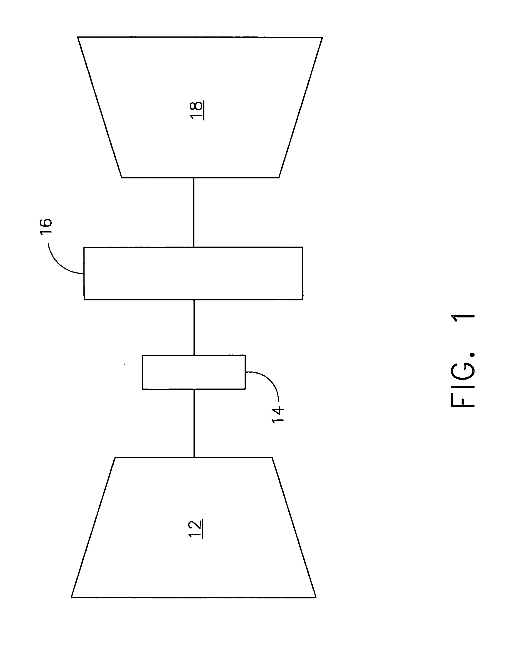
[0012]FIG. 1 is a schematic illustration of an exemplary turbine nozzle test assembly 10. Assembly 10 includes an inlet 12, a pre-swirl nozzle 14, a turbine nozzle 16, and an outlet arranged in a serial flow relationship. In operation, air flows through inlet 12 and pre-swirl nozzle 14. Pre-swirl nozzle 14 expands and thereby accelerates the air upstream from turbine nozzle 16. Air swirled by is channeled through turbine nozzle 16 to evaluate a parameter of turbine nozzle 16, such as, but not limited to, a flow loss of nozzle 16 and / or a performance of nozzle 16.

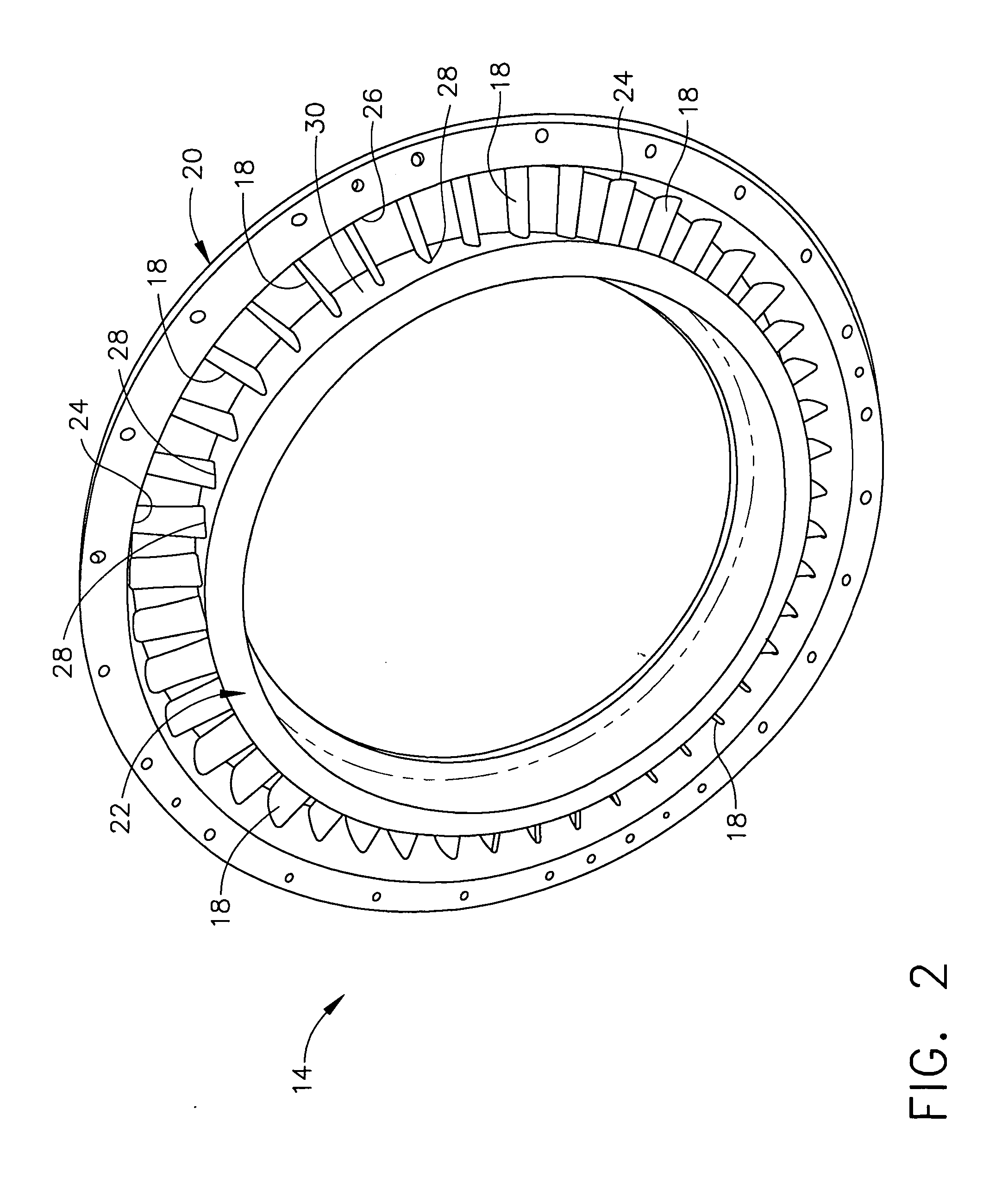
[0013]FIG. 2 is a perspective view of an exemplary pre-swirl nozzle 14 for use with the turbine nozzle test assembly 10 (shown in FIG. 1). Pre-swirl nozzle 14 includes a plurality of circumferentially spaced airfoils 18, sometimes referred to as blades, coupled together by an annular radially outer band 20 and an annular radially inner band 22. More specifically, each airfoil 18 extends between an airfoil tip 24 coupled to ...


PUM


Abstract

A method for fabricating an assembly having an airfoil extending radially outwardly from a member includes determining three-dimensional information of the airfoil, converting the three-dimensional information into a plurality of slices that each define a cross-sectional layer of the airfoil, successively forming each layer of the airfoil by fusing a metallic powder using laser energy, and coupling the airfoil to the member such that the airfoil extends radially outward from the member.

Description

BACKGROUND OF THE INVENTION [0001] This invention relates generally to stator and / or rotor assemblies, and more specifically to methods for fabricating stator and / or rotor assemblies. [0002] At least some known gas turbine engines include a compressor, a combustor, and at least one turbine. The compressor compresses air which is mixed with fuel and channeled to the combustor. The mixture is then ignited for generating hot combustion gases, and the combustion gases are channeled to the turbine which extracts energy from the combustion gases for powering the compressor, as well as producing useful work to propel an aircraft in flight or to power a load, such as an electrical generator. [0003] The turbine includes a rotor assembly and a stator assembly. The rotor assembly includes a plurality of airfoils, sometimes referred to as rotor blades, extending radially outward from a disk. More specifically, each rotor blade extends radially between a platform adjacent the disk, to a tip. A c...

Claims


Application Information

Patent Timeline
IPC IPC(8): B23P15/04
CPCB22F3/1055B22F5/04B23P15/006B23P15/02Y10T29/4932F01D5/34F05D2230/22F05D2230/50F01D5/147Y02P10/25B22F10/28
Inventor JOHNSON, MICHAEL R.
Owner GENERAL ELECTRIC CO
Why Eureka
Try Eureka