
Oral respirator device and method for mask-free filtering of particulates from breathed air

a respirator and air filter technology, applied in the direction of breathing filter, breathing protection, protective clothing, etc., can solve the problems of inconvenient use, high manufacturing and maintenance costs, and inability to meet the needs of air quality control,

Inactive Publication Date: 2007-07-19
TEIBEL JEFFREY L
View PDF53 Cites 12 Cited by
  • Summary
  • Abstract
  • Description
  • Claims
  • Application Information

AI Technical Summary

Benefits of technology

[0016] Thus, having broadly outlined the more important features of the present invention in order that the detailed description thereof may be better understood, and that the present contribution to the art may be better appreciated, there are, of course, additional features of the present invention that will be described herein and will form a part of the subject matter of the claims appended to this specification.

Problems solved by technology

For example, when a podiatrist performs certain procedures on the feet and toenails, these procedures often generate particulates that may be carriers of infectious organisms.
Other prior art respiration devices are relatively complex, often involving valves, power supplies, motors, fans and electronic parts that render them costly to manufacture and maintain.
They may also require specialized filters that are costly and not readily available through established supply channels in the medical and industrial community.
Surgical-type masks typically worn by medical professionals are relatively effective as filtering systems, however, they have many drawbacks.
Most importantly, users often find the masks uncomfortable.
They may have insufficient venting and cause excess heat build-up, cause fogging if the user wears eyeglasses or magnifying devices, cause bothersome reflections, cause sweating, irritate the skin, tangle in the hair, and interfere with eyeglasses or other medical and nonmedical equipment that is affixed to the head and neck.
These face masks inhibit the ability of the medical professional to freely communicate with the patient, especially with hearing impaired patients who may rely partially or entirely on visual cue perception (e.g. lip reading) for communication.

Method used


Image

  • Oral respirator device and method for mask-free filtering of particulates from breathed air
  • Oral respirator device and method for mask-free filtering of particulates from breathed air
  • Oral respirator device and method for mask-free filtering of particulates from breathed air

Examples


embodiment 1300

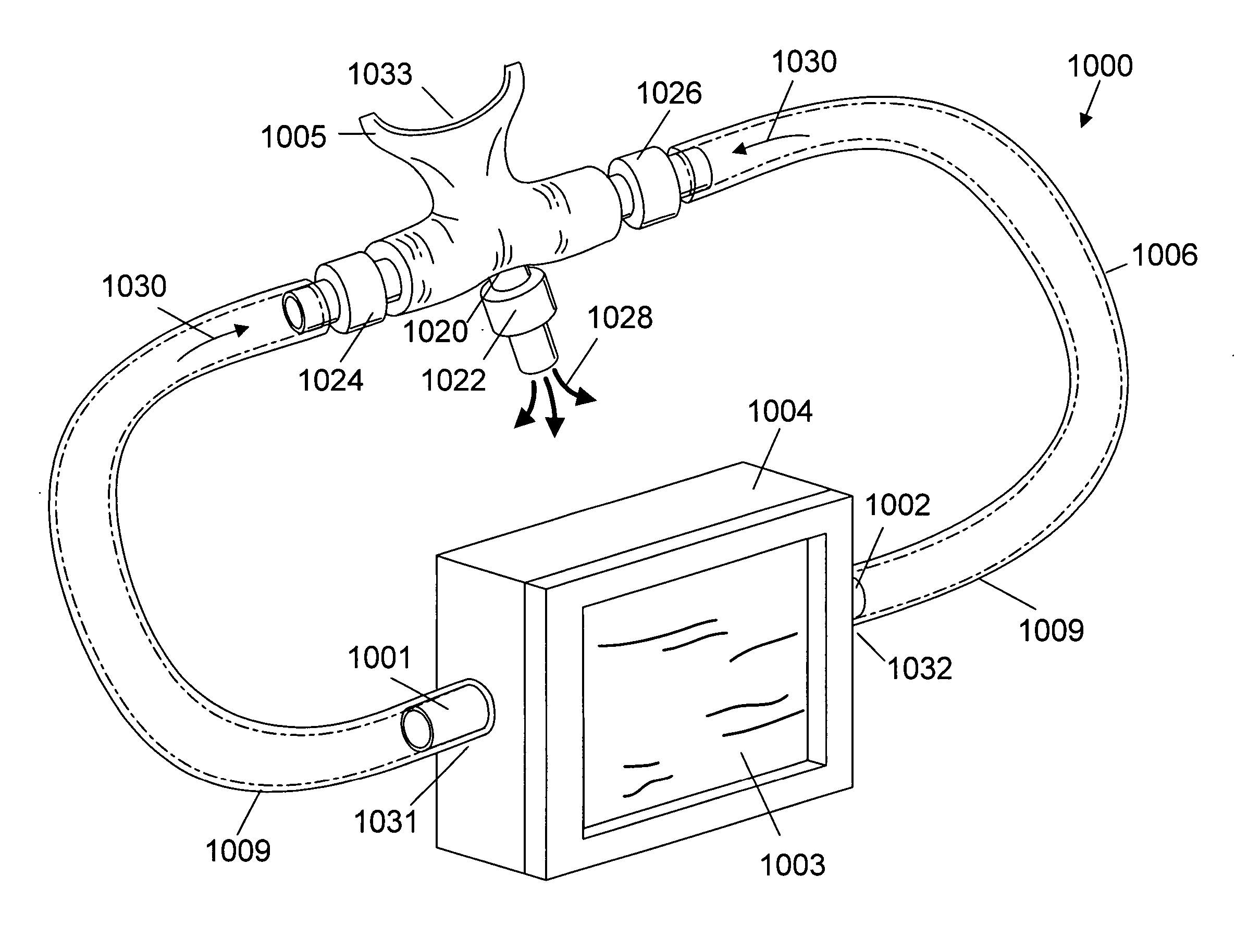
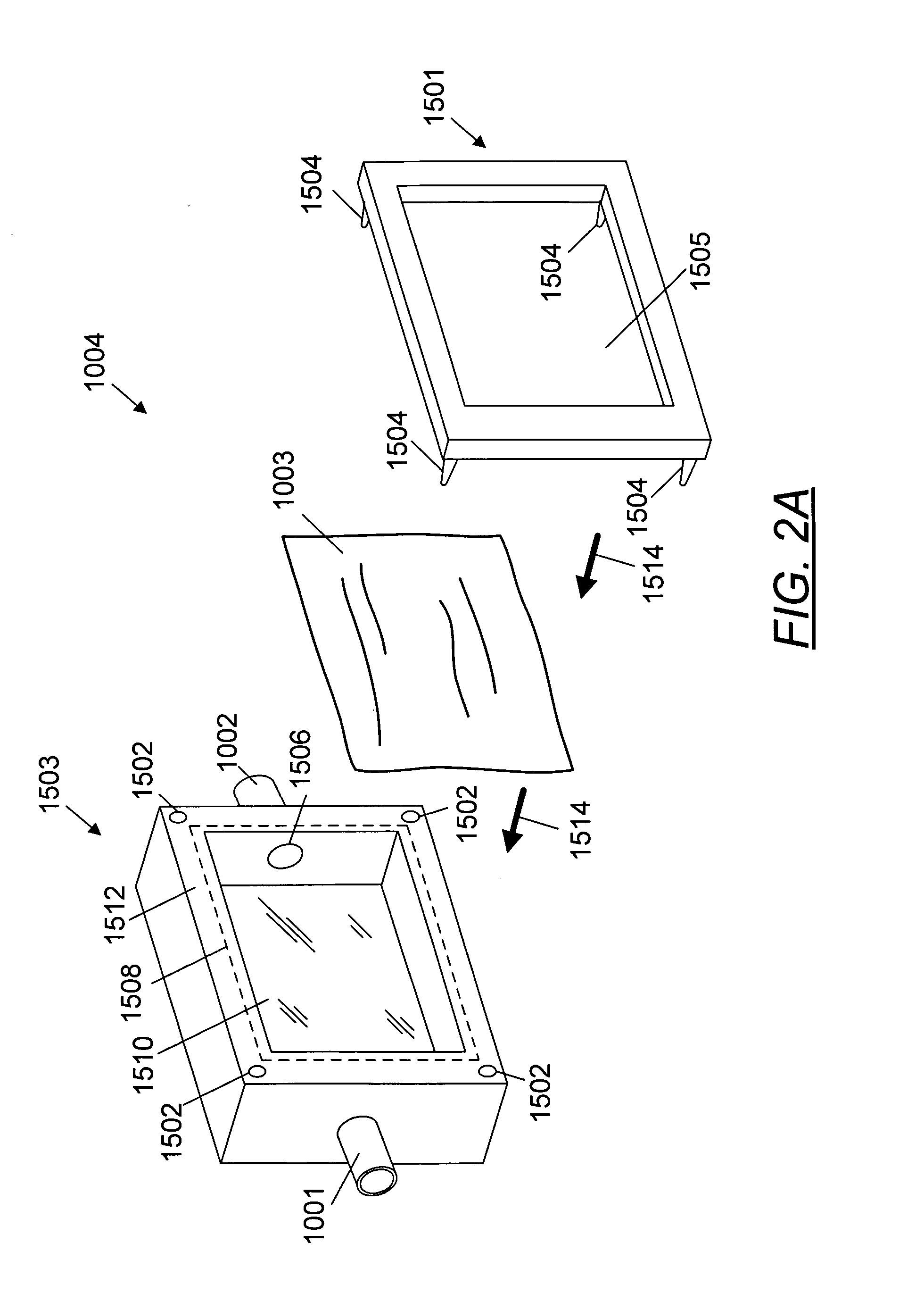
[0111]FIG. 11 depicts an alternative embodiment 1300 of the housing of device 100. In one embodiment depicted, the shape of the housing is a rectangular cube with open side 1302 (there is no wall). As will be apparent, the device is substantially the same as described previously except that the housing 1300 is a unitary piece and the filter 110 is secured to the housing 1300 by straps, ties or rubber bands 124, 128, 126, 130 to the open side 1302 of the housing. The straps, ties or rubber bands fit within small channels 132, 136, 134, 138 that surround the entire periphery of the device. These channels keep the straps, ties or rubber bands from dislocating, thus keeping the filter 110 tightly secured to the housing. In one embodiment, these channels have a diameter of from about one to about 4 millimeters and are disposed at a distance of from about 4 to about 30 millimeters from the outside edge of each side.

[0112] Referring again to FIG. 11, as will be apparent, many configuration...

embodiment 1400

[0119]FIG. 10 depicts a modification to the embodiment depicted in FIG. 9. As will be apparent, the embodiment 1400 in FIG. 10 is substantially identical to that in FIG. 9 except that there are two apertures 716 along the surface of the two opposing side panels 708, 710 and back panel 714. (These apertures are substantially the same as apertures 716 of FIG. 7.) These apertures 716 may be disposed along the surface of the two opposing side panels 708, 710 and back panel 714 in any location that is convenient for the manufacturer or user. Applicant believes that a somewhat central location provides the optimum utility.

[0120] Referring again to FIG. 9, in some embodiments, a one-way respiratory valve 750 is operably connected to the air inlet hole 716. Such respiratory valves are well-known and any suitable one-way valve may be used. By way of example, but not limitation, one may use a valve according to the teachings of U.S. Pat. No. 4,172,467 (Respirator valve for respirators); U.S. ...

embodiment 800

[0123]FIG. 12 depicts a detailed view of a portion of the housing and the oral interface depicted in FIG. 3 and how such parts are operably connected. Referring to FIG. 12 and the embodiment 800 depicted, the male portion 104 of the oral interface (or the unitary piece in some embodiments) is operably connected to the housing 102 at air inlets 114, 116 by press or snap fitting to form a substantially airtight seal. The male portion 104 fits within the female portion 106 of the oral interface by press or snap fitting to form a substantially airtight seal.

[0124] In an embodiment depicted in FIGS. 13A and 13B, the oral interface 900, 950 comprises a plastic tube with a lumen diameter 915, 965 of from about one to about 10 millimeters, more preferably from about four millimeters to about ten millimeters, and most preferably from about 5 to about 7 millimeters. In oral interface 950, the diameter 965 is divided equally between the two bifurcated parts. By way of example, but not limitati...


PUM


Abstract

An oral respirator device and method for mask-free filtering of particulates from breathed air. A surgical mask is removably disposed within a housing. The housing has an air chamber, a first air inlet, a second air inlet, and a means of securing the surgical mask filter. Operably attached to the housing is an oral interface (such as a surgical tube). In one embodiment, the oral interface has three openings, one of which is a mouthpiece while the other two openings, the ends of the tube, are connected to the air inlets of the housing. Environmental air enters the air chamber of the housing via the filter becoming filtered breathable air. The filtered breathable air enters the mouth of the user via the oral interface. In one embodiment, one-way valves are operatively connected to the oral interface.

Description

FIELD OF THE INVENTION [0001] An oral respirator device and method for mask-free filtering of particulates from breathed air comprising a filter removably disposed within said oral respirator, wherein said filter is a surgical mask, a housing for receiving and confining said filter comprising an air chamber, a first air inlet, a second air inlet, and a means of securing said filter, an oral interface comprising a tubular member operatively connected to said housing, wherein said tubular member comprises a first opening, a second opening, and a third opening, a first valve operatively connected to said tubular member, a second valve operatively connected to said tubular member, wherein said oral interface enables a user to breathe through said respirator, and wherein said oral respirator filters particulates from breathed air. BACKGROUND OF THE INVENTION [0002] In environments having noxious particulates suspended in the air, filtration devices are commonly employed to filter the air...

Claims


Application Information

Patent Timeline
Patent Type & Authority Applications(United States)
IPC IPC(8): A61M16/00A62B23/02
CPCA41D13/11A61M16/107A61M16/1065A62B23/00
Inventor TEIBEL, JEFFREY L.
Owner TEIBEL JEFFREY L
Learn More