Diagnostic and control system for a patient support

a control system and patient technology, applied in the field of hospital equipment systems, can solve the problems of time-consuming and costly, and the form of monitoring and potentially diagnosing problems of patient supports

Active Publication Date: 2007-07-19
STRYKER CORP
View PDF11 Cites 74 Cited by
  • Summary
  • Abstract
  • Description
  • Claims
  • Application Information

AI Technical Summary

Problems solved by technology

This form of monitoring and potentially diagnosis of problems with a patient support can be both time consuming and costly.

Method used


Image

  • Diagnostic and control system for a patient support
  • Diagnostic and control system for a patient support
  • Diagnostic and control system for a patient support

Examples


example i

The Use of Loads Cells and Tilt Sensors to Monitor Patients on a Patient Support

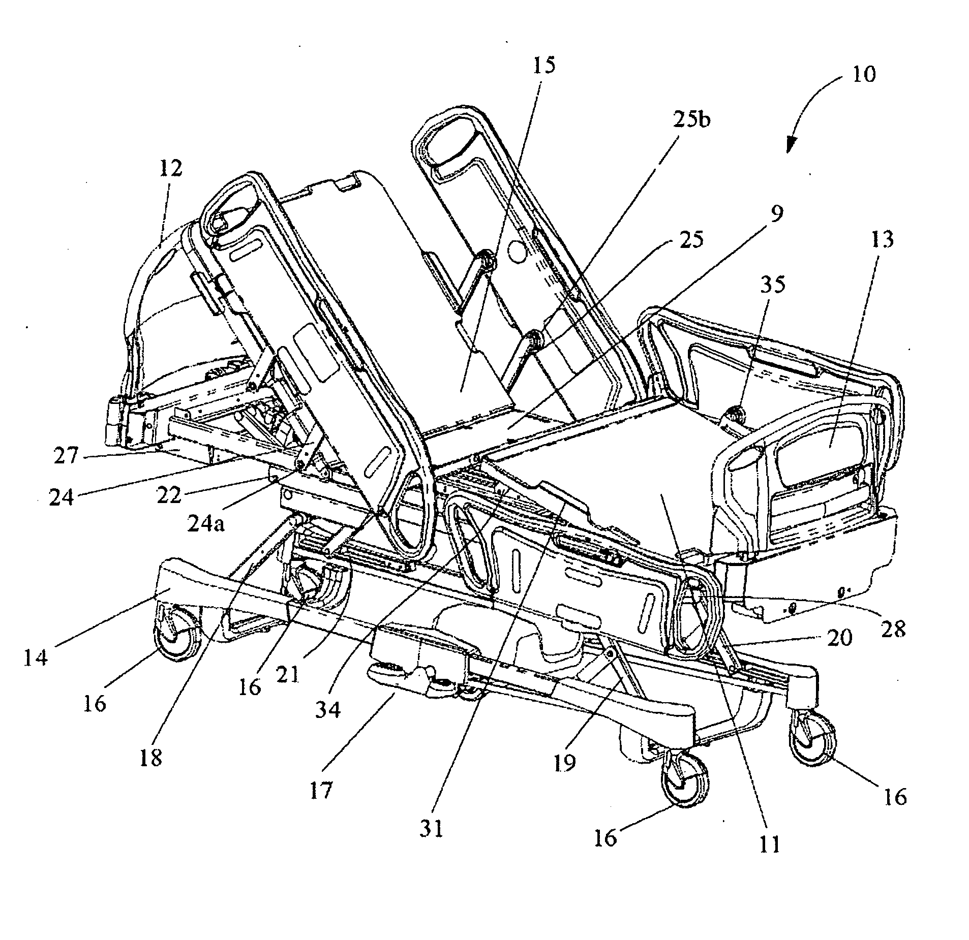
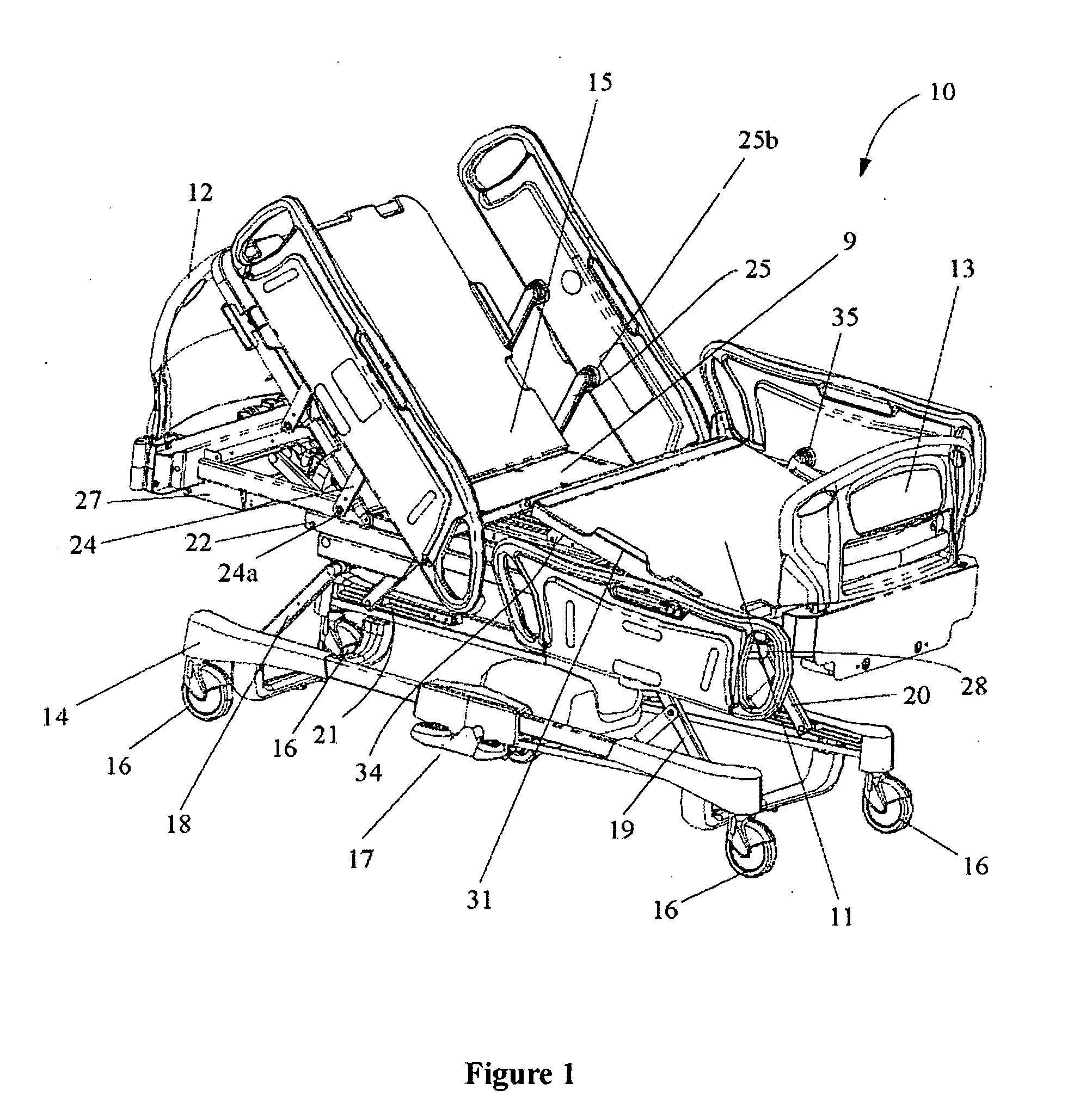
[0110] A patient support according to the present disclosure is shown in FIG. 1. The patient support with a head end and a foot end comprises a lying surface supported by a frame system. It also comprises a pair of head end siderails, a pair of foot end siderails, a headboard, a footboard, a power system and a communication system. The frame system comprises a lying surface support moveably connected to a load frame by an articulation system providing means for pivoting sections of the lying surface support relative to the load frame, a head end support arm pivotally attached to the head end of the load frame, a mobile frame translationally attached to foot end of the load frame, an intermediate frame being operationally connected to the load frame by a plurality of load cells and movably connected to a base frame by an elevation system, the elevation system providing a means for raising and lowering th...


PUM


Abstract

The present invention provides a diagnostic and control system for a patient support, wherein the patient support comprises one or more of a plurality of electronic elements including for example, load sensors, tilt sensors, actuators for adjusting patient support angles and the like, in addition to other electronic elements for example. The diagnostic and control system according to the present invention can enable the specific control of each of these electronic element for desired operation thereof and further can enable the monitoring of the operating conditions of these electronic elements and additional patient support conditions. The diagnostic and control system further enables the evaluation and determination of the existence of one or more faults relating to the operation of the patient support and the respective one or more electronic elements, for example the existence of a fault can be conveyed to an operator in a form of an error message. The diagnostic and control system can subsequently evaluate the detected fault and can determine for example a cause thereof and a potential remedy. In this manner the diagnostic and control system according to the present invention can provide the evaluation of the detected fault and subsequently provide the operator or technician with a remedy for the fault detected, thereby reducing the downtime of a patient support including the diagnostic and control system according to the present.

Description

FIELD OF THE INVENTION [0001] The present invention pertains to hospital equipment systems and in particular to a hospital equipment system having a patient support status system for controlling and diagnosing the status of a hospital patient support. BACKGROUND [0002] Temporary and long term care of a patient generally requires that the patient be supported for the duration of the treatment. Currently available hospital beds are equipped with a number of complex mechanical and electrical subsystems which provide positioning, weight monitoring, and other functions related to patient's care. Despite their inherent complexity, these systems need to be easy to interact with and used by the caregiver. The ease of use and operation is of critical importance, particularly in emergency situations. Due to the complexity and required minimal downtime for these forms of beds, the status of such systems needs to be constantly monitored, which currently is performed by technicians in order to e...

Claims


Application Information

Patent Timeline
Patent Type & Authority Applications(United States)
IPC IPC(8): G08B23/00G16Z99/00
CPCA61G7/015A61G7/018A61G7/0507A61G2007/0514A61G2007/0527A61G2203/46A61G2203/32G06F19/3412A61G2203/36A61G2203/42A61G2203/44A61G2203/12A61G7/0514A61G7/0527G16H40/40G16Z99/00
Inventor DIONNE, JEAN-PAULTREPANIER, NADINELANDRY, LUC
Owner STRYKER CORP
Why Eureka
Try Eureka