Systems and methods for controlling transient response in the output of a noise shaper

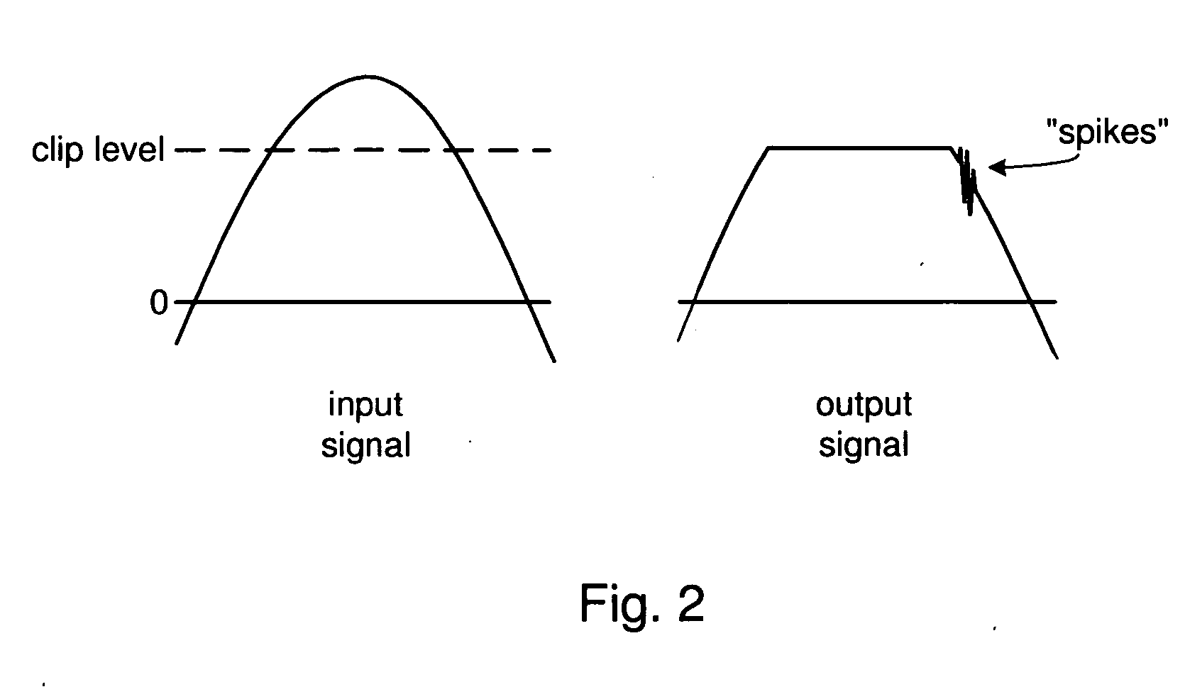
a noise shaper and transient response technology, applied in the field of noise shapers, can solve the problems of spikes in signal, filter actually introduces a relatively large error, artifacts in quantizer output signals, etc., and achieve the effect of reducing or eliminating spikes or other undesirable transient responses

Active Publication Date: 2007-07-19
INTERSIL INC
View PDF3 Cites 4 Cited by
  • Summary
  • Abstract
  • Description
  • Claims
  • Application Information

AI Technical Summary

Benefits of technology

[0012] This disclosure is directed to systems and methods implemented in a multi-bit digital noise shaper for reducing or eliminating spikes or other undesirable transient response when the noise shaper exits a clipping state. (It should be noted that references herein to “spikes,”“artifacts” or the like should be construed to include any type of undesirable transient response.) In one embodiment, the noise shaper includes a quantizer and a filter similar to conventional noise shapers, and a filter control unit that detects clipping in the quantizer and dynamically adjusts the allowable range of the internal state values of the filter. In this embodiment, a clipping mechanism is provided for each state value within the filter to clip the state value if it exceeds a corresponding clipping level. The clipping level for each state value is modifiable so that it is set to a first (e.g., lower) level when the quantizer is clipping, and a second (e.g., higher) level when the quantizer is not clipping. The clipping level for each state value may be transitioned either immediately or gradually from a current level to a target level (which is lower when the quantizer is clipping, and higher when the quantizer is not clipping.)

Problems solved by technology

One of the problems that may be experienced in a noise shaper as shown in FIG. 1 relates to the quantizer clipping the output signal.
When the signal drops below the level at which the quantizer clips the signal, however, the filter is still trying to provide feedback based on a large difference between the input and output signals.
As a result, the filter actually introduces a relatively large error.
As the filter processes this error, the filter signal may oscillate between being too high and too low, causing spikes or other undesirable artifacts in the quantizer output signal.
It can be seen that the windup of the internal state of the noise shaper causes spikes in the signal when the noise shaper stops clipping the signal.
There is, however, a tradeoff—the more the state values are limited, the less wind-up of the internal state (and spikes or artifacts in the output) will occur, but the filter also has less freedom to compensate for the difference between the input and output signals.
Also, if clipping of the internal state occurs often, this may cause noise in the output.
If the state values are less restricted, the filter will be able to better compensate for the difference between the input and output signals, but the spikes or artifacts will be worse.
This conventional solution is not optimal for either the problem of spikes and artifacts, or the generation of the feedback signal.
Moreover, this solution can be difficult to implement, as it is a tedious process to manually determine the levels at which each of the state values should be limited.

Method used


Image

  • Systems and methods for controlling transient response in the output of a noise shaper
  • Systems and methods for controlling transient response in the output of a noise shaper
  • Systems and methods for controlling transient response in the output of a noise shaper

Examples


Embodiment Construction

[0024] One or more embodiments of the invention are described below. It should be noted that these and any other embodiments described below are exemplary and are intended to be illustrative of the invention rather than limiting.

[0025] As described herein, various embodiments of the invention comprise systems and methods for reducing or eliminating undesirable transient response in clipped audio signals in digital amplifiers.

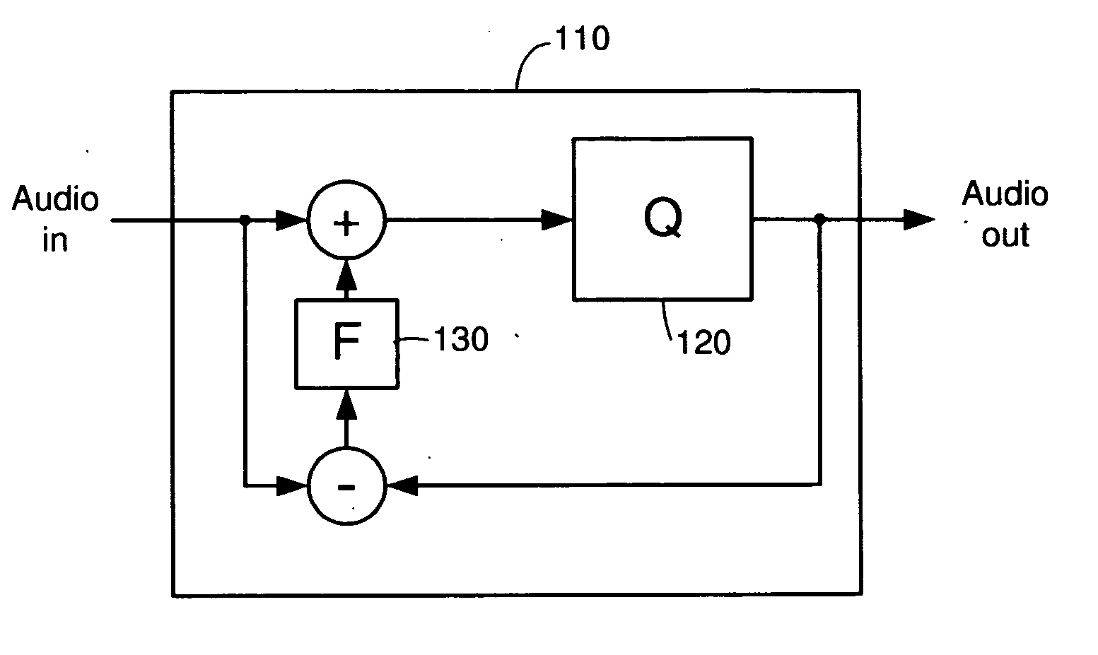
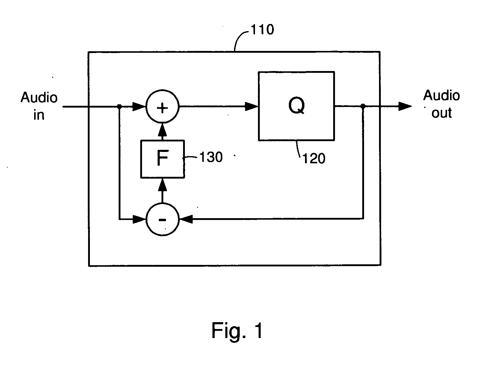
[0026] In one embodiment, a digital pulse width modulation (PWM) amplifier includes a noise shaper that quantizes and reshapes the noise spectrum of an input audio signal to produce an output audio signal. The noise shaper includes a quantizer configured to quantize the input audio signal and clip the signal if necessary. The noise shaper also includes a filter configured to receive a difference signal (corresponding to the difference between the output audio signal and the input audio signal,) filter the difference signal and add the filtered feedback signal ...


PUM


Abstract

Systems and methods implemented in a multi-bit digital noise shaper for reducing or eliminating undesirable transient response when the noise shaper exits a clipping state. In one embodiment, the noise shaper includes a quantizer, a filter, and a filter control unit that detects clipping in the quantizer and dynamically adjusts the allowable range of the internal state values of the filter. In one embodiment, a clipping mechanism is provided for each state value within the filter to clip the state value if it exceeds a corresponding clipping level. The clipping level for each state value is lower when the quantizer is clipping, and higher when the quantizer is not clipping. The clipping level for each state value may be transitioned either immediately or gradually from a current level to a target level (which is lower when the quantizer is clipping, and higher when the quantizer is not clipping.)

Description

BACKGROUND [0001] 1. Field of the Invention [0002] The invention relates generally to noise shapers such as those used in digital audio amplifiers and more particularly to systems and methods for controlling transient response in the output of a noise shaper when the noise shaper stops clipping an output signal. [0003] 2. Related Art [0004] Digital amplifiers may process signals in various ways. For instance, it is common for pulse width modulated (PWM) digital amplifiers to use a noise shaper to quantize an input signal (i.e., to convert the signal from an N-bit signal to an M-bit output signal that may have a maximum amplitude.) The noise shaper also provides some feedback based on the filtered difference between the input and output signals to shape the noise spectrum of the output signal. [0005] Referring to FIG. 1, a functional block diagram illustrating a typical structure for a conventional noise shaper is shown. Noise shaper 110 normally includes a quantizer 120 and a filter...

Claims


Application Information

Patent Timeline
Patent Type & Authority Applications(United States)
IPC IPC(8): H03M3/00G10L19/00G10L19/03G10L21/0332G10L21/034G10L21/0364
CPCH03M7/3026H03M7/3011
Inventor ANDERSEN, JACK B.
Owner INTERSIL INC
Why Eureka
Try Eureka