Printing apparatus and printing method

a printing apparatus and printing method technology, applied in the direction of digital output to print units, instruments, digital computers, etc., can solve the problems of not being able to adjust the print position of an image on a sheet of only a specific page, and the print process conditions of one print job in the printing apparatus can not be partially changed by conventional techniques, so as to improve user friendliness

Inactive Publication Date: 2007-07-19
CANON KK
View PDF10 Cites 58 Cited by
  • Summary
  • Abstract
  • Description
  • Claims
  • Application Information

AI Technical Summary

Benefits of technology

[0008]The present invention enables to provide a printing apparatus and printing method capable of partially changing the print process conditions of a print job containing image data of pages, and improving user friendliness.

Problems solved by technology

However, the conventional techniques cannot partially change the print process conditions of one print job in the printing apparatus after transferring the print job to the printing apparatus.
These techniques cannot adjust the print position of an image on a sheet of only a specific page.
The conventional techniques can partially change print process conditions, but the print process conditions are set when generating a print job and cannot be changed after transmitting a print job to the printing apparatus.

Method used


Image

  • Printing apparatus and printing method
  • Printing apparatus and printing method
  • Printing apparatus and printing method

Examples


first embodiment

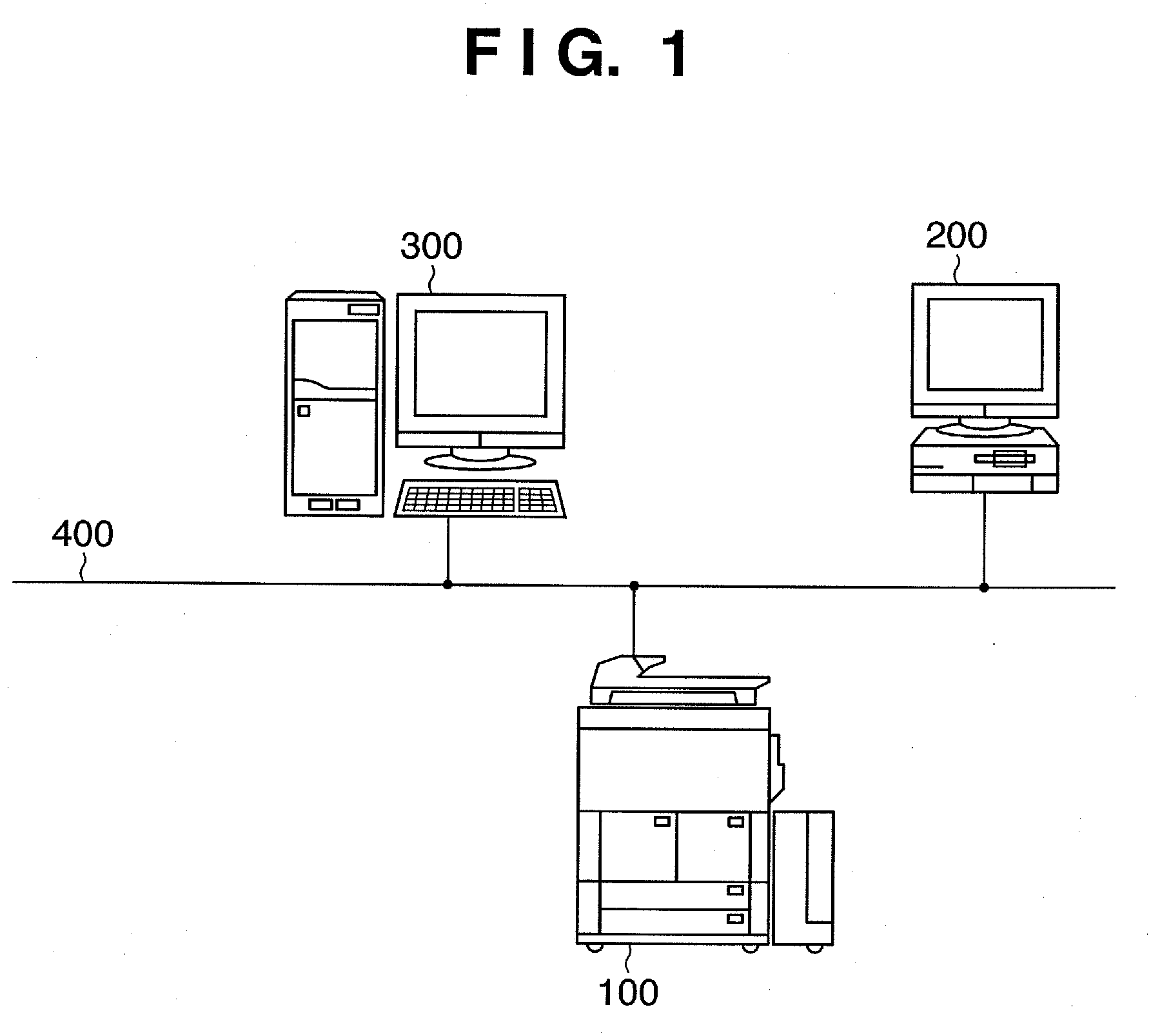
[0085]FIG. 1 is a block diagram showing an example of the basic configuration of an overall printing system according to the first embodiment of the present invention. As shown in FIG. 1, according to the first embodiment, the printing system includes an MFP (MultiFunction Peripheral) 100, client PC 200, and print server 300, which connect to a network 400.

[0086]The MFP 100 has various functions such as scanning, printing, and copying functions. The client PC 200 plays the role of editing an input application file, issuing a print instruction, or inputting a print ready file, and the role of assisting monitoring and control of devices and jobs managed in the print server. A print job generated by the client PC 200 is transferred to the MFP 100 directly or via the print server 300.

[0087]The print server 300 has two roles. One role is to transmit / receive information between the MFP 100 and the client PC 200. The print server 300 receives image information, setting information, and the...

second embodiment

[0198]In the first embodiment, the client PC 200 or print server 300 inputs a print job. The second embodiment uses a scanner unit to input a print job.

[0199]The second embodiment will describe a scanner unit using an ADF (Auto Document Feeder), but is also applicable to a scanner unit which receives sheets one by one from the platen.

[0200]FIGS. 19 and 20 are perspective and sectional views, respectively, showing the structure of the ADF employed in the second embodiment.

[0201]In FIGS. 19 and 20, a document is set on the support surface of a document tray 1901 in a document stacking section 2001. A document sensor detects that the document is set. The document sensor is interposed between pickup rollers 2002 and a sheet feed roller 2003 (to be described later).

[0202]A sheet feed section 2004 separates one top sheet from a document bundle by frictional separation, and conveys the sheet to registration rollers 2005. When feeding a document sheet, the pickup rollers 2002 move down onto...

third embodiment

[0222]The first embodiment has described the print process condition change method using the windows of FIGS. 9 to 12. The third embodiment will explain another print process condition change method.

[0223]FIG. 23 shows a modification of the window in FIG. 9. FIG. 23 shows a window displayed when selecting a “hold list”2020 by a user operation in a window displayed on an operation unit 120 of a printing apparatus. A hold queue serving as part of the storage area of a document management unit 114 in an MFP 100 stores a print job hold-designated by a printer driver. A “hold job list”2021 is a list of jobs stored in the hold queue. The “hold job list”2021 displays the print process conditions of each print job (e.g., a job name, a user name, the number of pages, and a date and time when the job is stored). The contents of the displayed print process conditions comply with job ticket information generated by the printer driver.

[0224]A print job list 2022 is displayed at a lower portion i...


PUM


Abstract

This invention provides a printing apparatus and printing method capable of partially changing the print process conditions of a print job containing image data, and improving user friendliness. To accomplish this, a printing apparatus such as an MFP having a printing unit for printing based on a print job receives a print job containing image data of pages. When setting the print process conditions of the print job, the first print process conditions of the first page group of pages and the second print process conditions of the second page group of pages are set to different conditions. Image data of the first page group are printed under the first print process conditions, whereas image data of the second page group are printed under the second print process conditions.

Description

BACKGROUND OF THE INVENTION[0001]1. Field of the Invention[0002]The present invention relates to a printing apparatus and printing method.[0003]2. Description of the Related Art[0004]A commercial printing workflow accumulates, in a printing apparatus, a print job transferred to it and repeats test printing. The function of accumulating a print job in the printing apparatus is called a “hold function”. There is a demand for the ability to change print settings for each page when a printing apparatus having the hold function prints from an accumulated print job.[0005]To meet this demand, there is known a technique of sequentially queuing accepted print jobs and changing the print process conditions of a queued print job in accordance with a change instruction (Japanese Patent No. 3,344,150). There is also known a technique of setting print process conditions for each page when generating a print job based on document data (Japanese Patent Laid-Open No. 07-134707).[0006]However, the co...

Claims


Application Information

Patent Timeline
Patent Type & Authority Applications(United States)
IPC IPC(8): G06F3/12
CPCG06F3/1208G06F3/1288G06F3/1275G06F3/1263
Inventor UTSUNOMIYA, TAKESHITAKAHASHI, HIROYUKI
Owner CANON KK
Why Eureka
Try Eureka