Drum type washing machine

Active Publication Date: 2006-07-11
QINGDAO HAIER WASHING MASCH CO LTD +1
View PDF20 Cites 68 Cited by
  • Summary
  • Abstract
  • Description
  • Claims
  • Application Information

AI Technical Summary

Benefits of technology

[0009]In view of the above problems, the main object of the present invention is to improve the user-friendliness of drum type

Problems solved by technology

About the above drum type washing machine, many consumers are dissatisfied because of the difficulty in loading or unloading clothes.
With this design, the difficulty in loading or unloading clothes cannot be completely eliminated even by placing the washing machine on a dedicated platform.
These structures, however, cannot yield a satisfactory result for those who are accustomed to the user-friendly whirl type washing machines.
Another problem is related to the following washing

Method used


Image

  • Drum type washing machine
  • Drum type washing machine
  • Drum type washing machine

Examples


first embodiment

[0077]the present invention is described referring to the drawings.

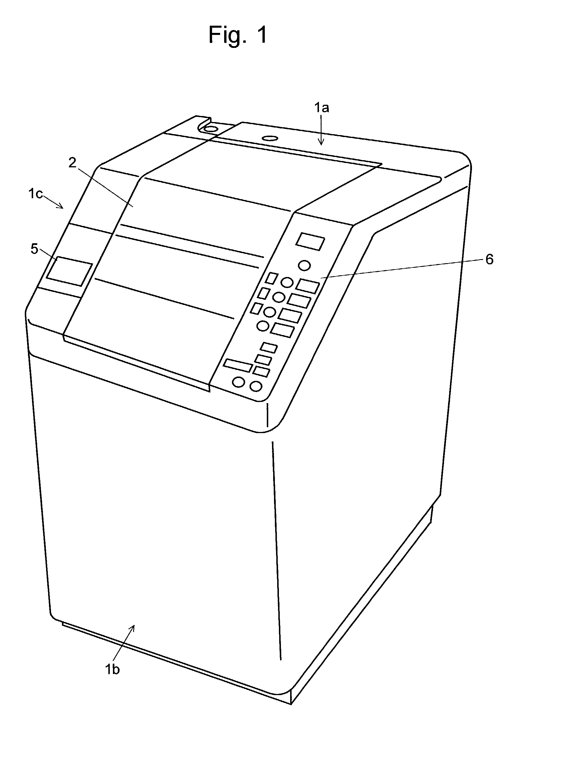
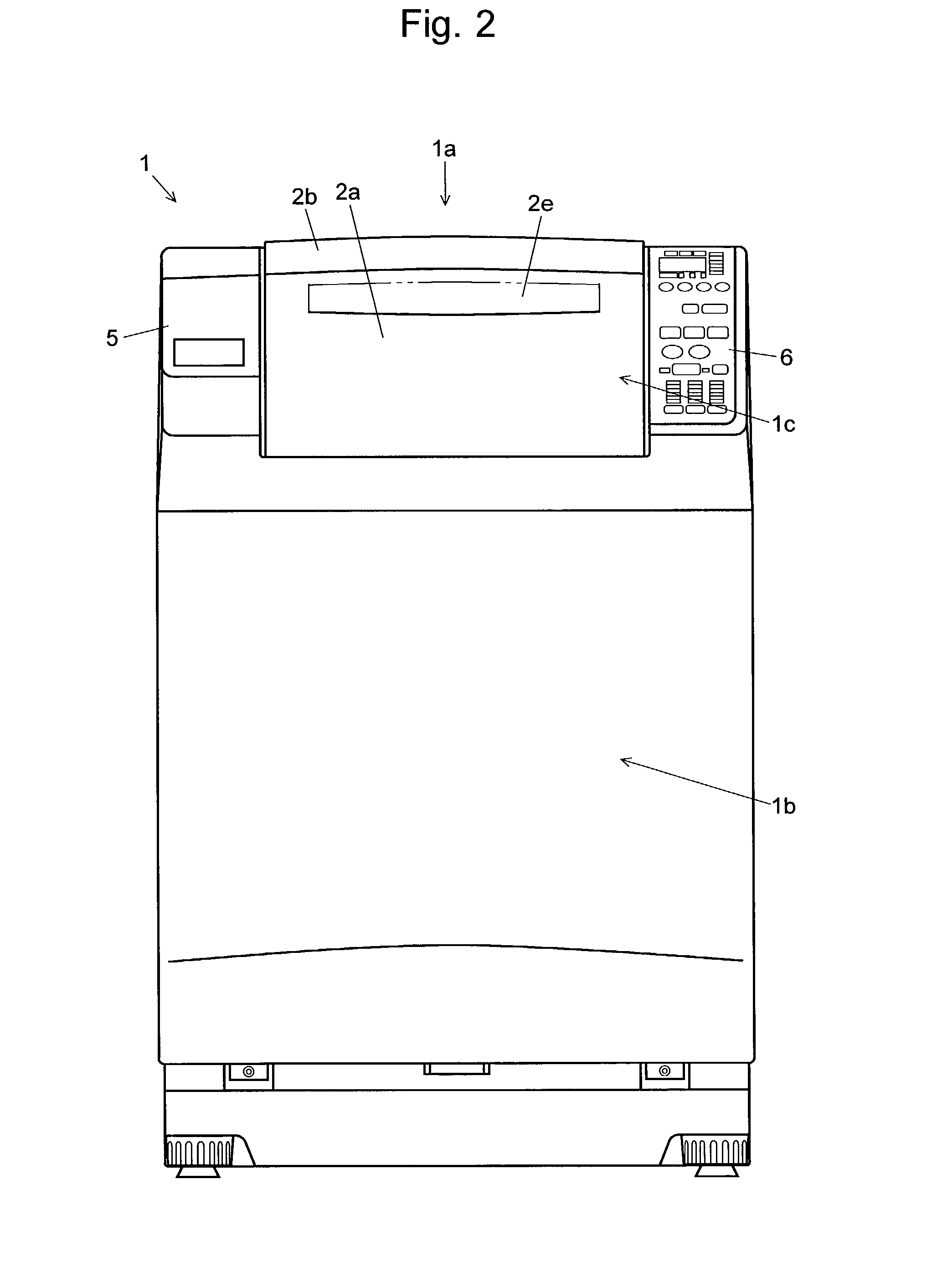
[0078]As shown in FIGS. 1 to 5, the washing machine of the first embodiment has a housing 1 having a part that declines with a slight roundness from the top 1a to the front 1b (the part is referred to as “the slope 1c” hereinafter). A large throw-in opening 3 (FIG. 5) is formed over the slope 1c and the horizontal part 1d across the bent part B (FIG. 4), and a lid 2 is provided to close the throw-in opening 3. When viewed from the side, the lid 2 as a whole looks like a dogleg with its front-side section declining downward.

[0079]As shown in FIG. 5, the lid 2 is composed of a first lid member 2a and a second lid member 2b, both of which are hinged by a central shaft 2d horizontally extending in the lateral direction. The rear end of the second lid member 2b is connected to a rear shaft 2c horizontally extending in the lateral direction in the rear part of the top 1a. To open the lid 2 that is in the closed position as...

second embodiment

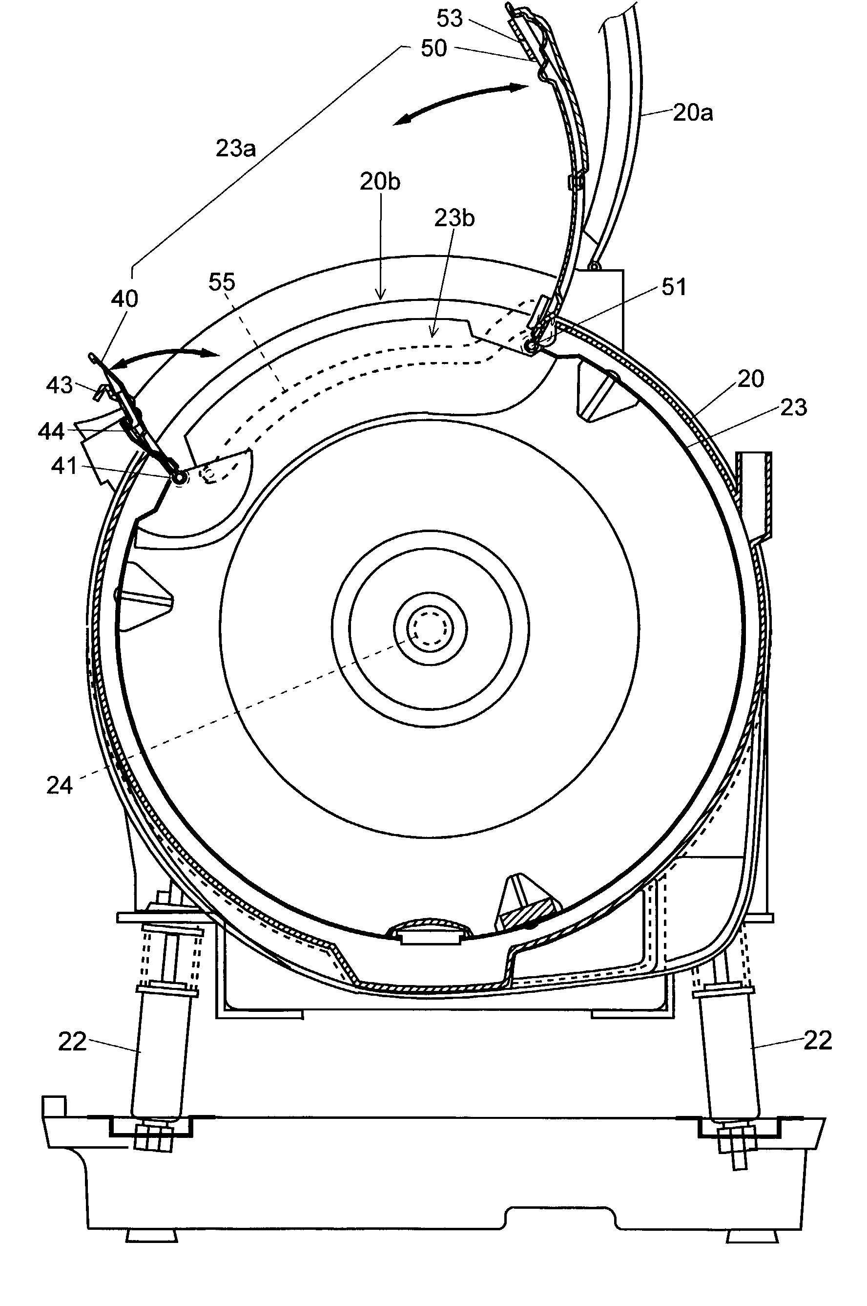
[0115]With the washing machine of the second embodiment, the tub door 110 and the drum door 310 are opened or closed as described above. The open / closed state of the tub door 110 is detected by a mechanism constructed in the housing 131 having the above-described projection 130. The housing 131 is fixed to the tub 20 opposite to the front edge of the tub door 110, as shown in FIGS. 20A and 20B.

[0116]In the housing 131 is provided with a pin 132 slidable in the front-back direction. The tip of the pin 132 protrudes from the wall of the housing 131 backward, or toward the front of the tub door 110. The pin 132 is pushed toward the tub door 110 by a movable plate 134 forced by a torsion coil spring 133. A switch 135 is placed in front of the movable plate 134.

[0117]When the tub door 110 is opened, no force is exerted on the pin 132 from behind (from the right side in FIG. 20). Therefore, the force of the spring 133 projects the pin 132 toward the tub door 110, and the movable plate 134...


PUM


Abstract

In a drum type washing machine, a drum 23 is mounted to rotate about a horizontal axis extending in the lateral direction in a tub 20. A tub opening 20b with a tub door 20a is formed in the tub 20 under the throw-in opening 3 formed in the front part of the top of the housing. A drum opening 23a with a drum door composed of a double door opening frontward and backward is formed in the peripheral wall of the drum 23. The drum 23 is stopped so that the drum opening 23b coincides with the tub opening 20b. The drum door 23a, forced into its opening direction, is held in a closed position by an engagement of a claw 43 and an engagement hole 53. When a user rotates a operation lever 63b for latching or unlatching the tub door 20, the drum door open/close mechanism 65 functions to make two rods 65a and 65b project or withdraw, whereby the drum door 23a is brought into an engaged or unengaged state. By this mechanism, the drum door 23a opens or closes with the opening or closing operation of the tub door 20a. Thus, the operation of the doors is simplified, and the laundry loaded into or unloaded out of the drum 23 by fewer working steps.

Description

[0001]The present invention relates to a drum type washing machine having a drum rotated about a horizontal or inclined axis. The drum type washing machine hereby may be one that is constructed to continuously perform the dual processes of washing to drying, like many commonly available drum type washing machines.BACKGROUND OF THE INVENTION[0002]A drum type washing machine has an outer tub, simply referred to as “a tub” hereinafter, in which a cylindrical basket drum is mounted to rotate about a horizontal or inclined axis. With the laundry loaded inside, the drum is rotated in the tub containing water. The drum thus rotating makes the laundry tumble, whereby the stain or the like is removed from the laundry. Well known conventional drum type washing machines have a substantially rectangular parallel-piped housing equipped with a front door that opens laterally to put clothes in. When the door is opened, a throw-in opening provided at an end of the drum becomes visible through an op...

Claims


Application Information

Patent Timeline
IPC IPC(8): D06F39/14D06F37/10D06F37/28D06F37/42
CPCD06F37/10D06F37/42D06F37/28
Inventor NAKAMURA, SATOSHIKAWAMURA, TAMOTSUNAKAGAWA, KENJIFUKUI, TAKASHITAKEUCHI, MAKOTOTAKEUCHI, HARUMIFUNADA, YORIHISAHONDA, KUNIOKI
Owner QINGDAO HAIER WASHING MASCH CO LTD
Why Eureka
Try Eureka