Connector

Active Publication Date: 2007-07-19
YAZAKI CORP
View PDF2 Cites 3 Cited by
  • Summary
  • Abstract
  • Description
  • Claims
  • Application Information

AI Technical Summary

Benefits of technology

[0011]The invention was made in view of these situations, and an object thereof is to provide a connector which enables the cancellation of locking of the retainer by the retainer operating jig, obviates the necessity of operating the retainer operating jig more than required so a

Problems solved by technology

Because of this, in order to perform a smooth and ensured operation, the construction and configuration of th

Method used


Image

  • Connector
  • Connector
  • Connector

Examples


Embodiment Construction

[0029]Hereinafter, the invention will be described by reference to an embodiment which is illustrated in the accompanying drawings.

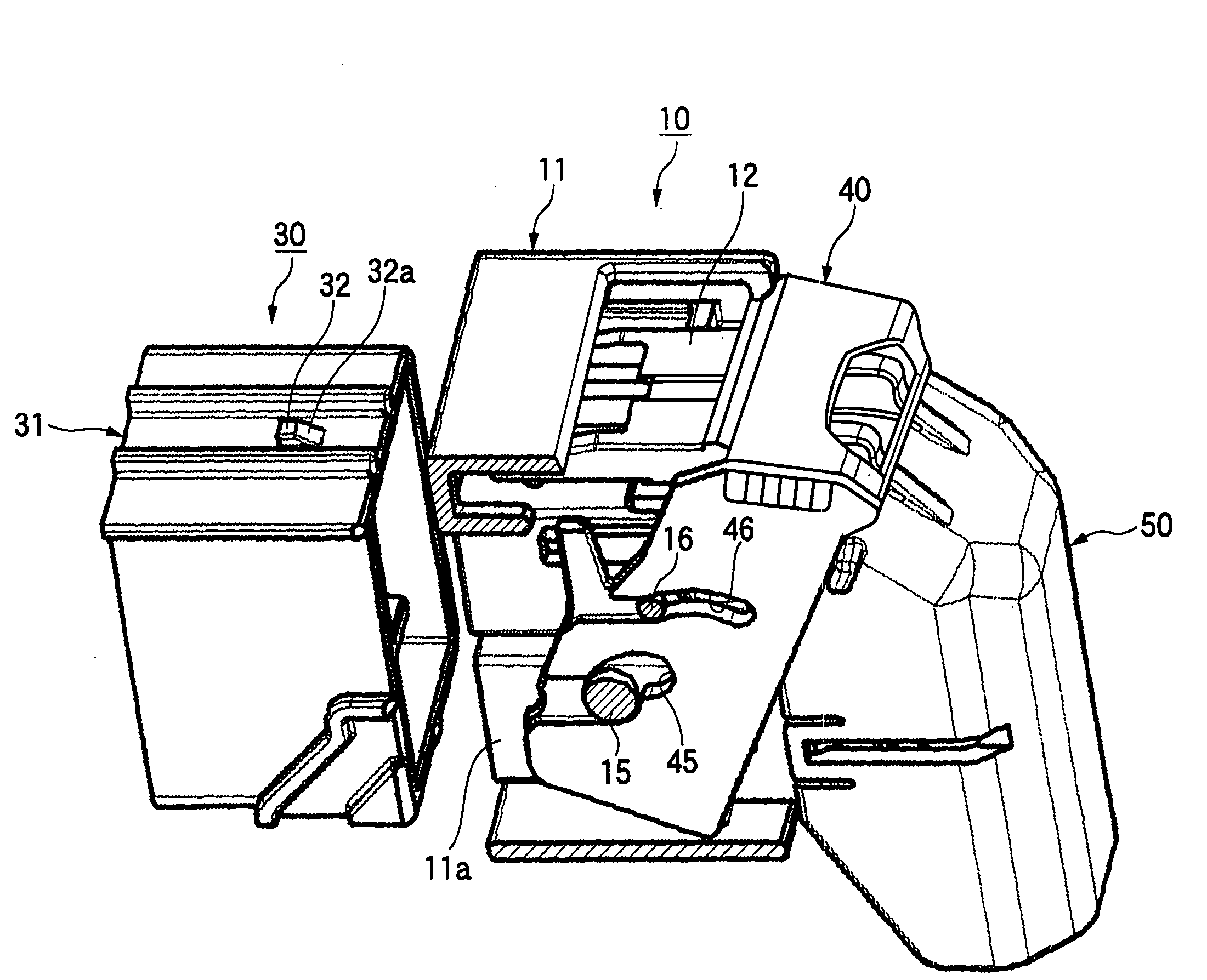
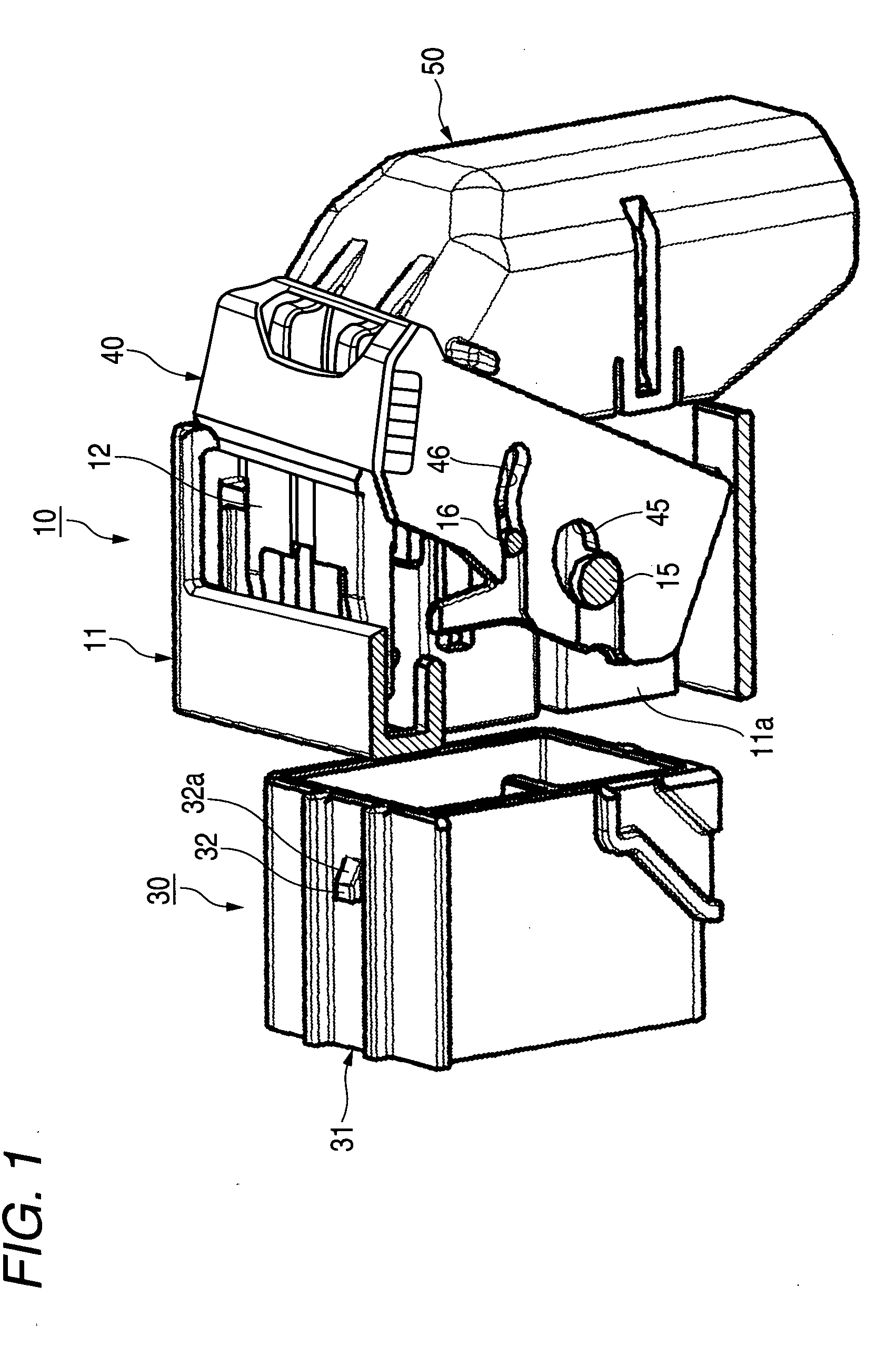
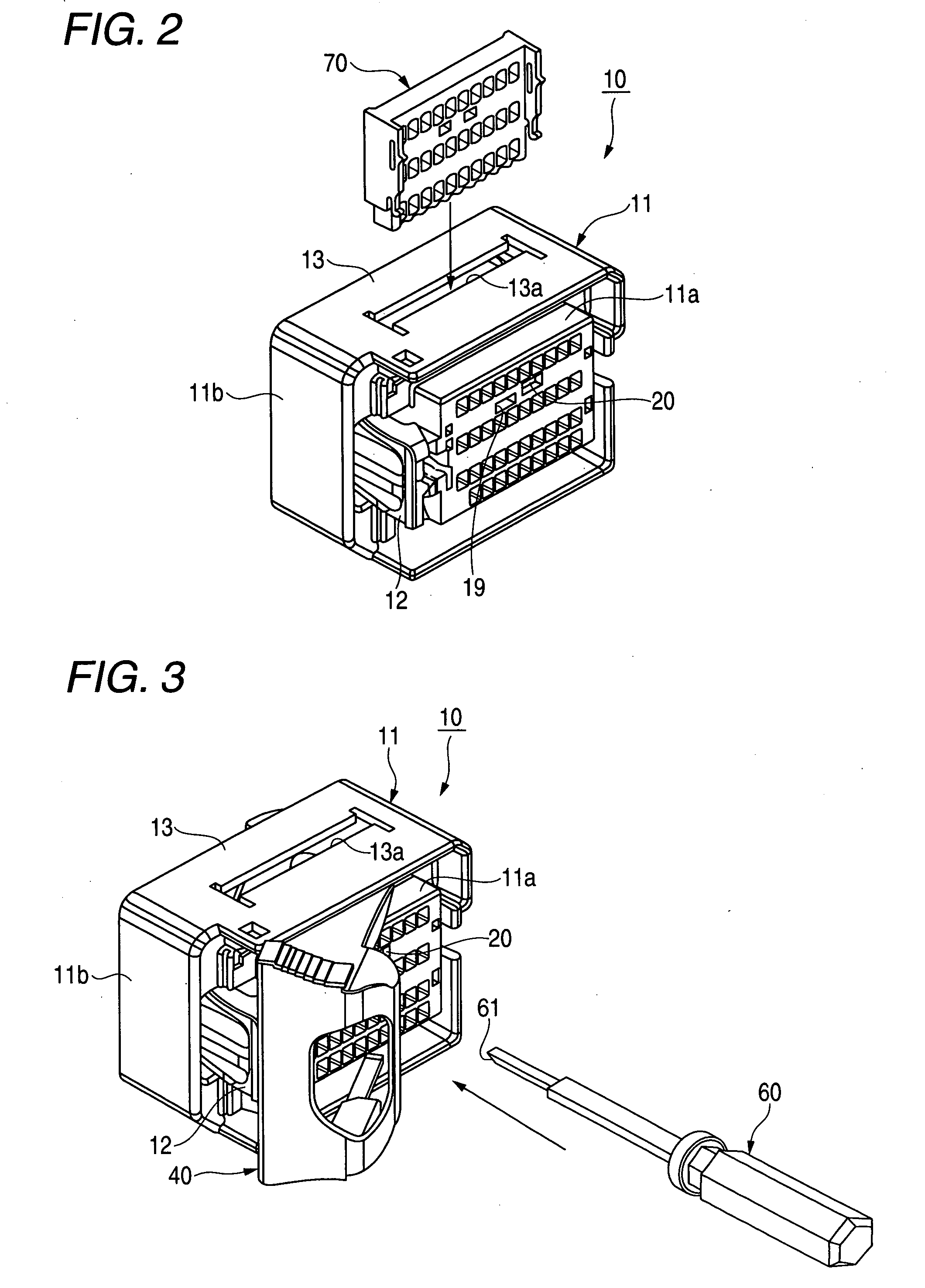
[0030]FIG. 1 is a perspective view of a connector of an embodiment of the invention with part of an outer housing removed therefrom which shows a state resulting before connectors are fitted together, FIG. 2 is a perspective view showing the state in FIG. 1 in which a retainer has not yet been assembled, FIG. 3 is a perspective view showing the state in FIG. 1 in which the retainer and a lever have been assembled with the lever located in a temporary locking position, and FIG. 4 is a sectional view of a main part of FIG. 1. In addition, FIGS. 5A and 5B show schematic sectional views of the main part of the connector in FIG. 1 which show the periphery of a temporary locking jig inserting hole for explanation of a displacing operation of a retainer from a proper locking position to a temporary locking portion by a retainer operating jig, in which FIG. 5A s...


PUM


Abstract

A temporary locking jig inserting hole which enables a retainer operating jig to be inserted thereinto from the outside is provided on a side of an inner housing of a female connector from which electric wires are drawn out in such a manner as to extend along a direction in which female terminals are inserted into the inner housing. In addition, a temporary locking retainer side tapered portion is provided on a retainer in such a manner as to correspond in position to the temporary locking jig inserting hole. In association with the insertion of the retainer operating jig from the temporary locking jig inserting hole, the temporary locking retainer side tapered portion is brought into sliding contact with a jig side tapered portion of the retainer operating jig, so as to displace the retainer which is being in a proper locking position to a temporary locking position.

Description

BACKGROUND OF THE INVENTION[0001]1. Field of the Invention[0002]The present invention relates to a connector in which a terminal inserted into a connector housing is locked by a retainer.[0003]2. Related Art[0004]Conventionally, connectors have been known (refer to, for example, JP-A-2003-51352). FIG. 7 is a sectional view which shows a connector and a retainer operating jig which are disclosed in JP-A-2003-51352.[0005]Referring to FIG. 7, in a connector, a retainer inserting opening 101 is provided in a female housing 100 in a direction (in FIG. 7, in a vertical direction) which intersects an inserting direction (in the figure, in a horizontal direction) of a female side terminal metallic fixture 110 at substantially right angles, and a retainer 120 is inserted from the relevant direction.[0006]A jig inserting opening 102 is provided in an edge portion of the retainer inserting opening 101 along an inclined direction in such a manner as to communicate with an engagement hole 121 pr...

Claims


Application Information

Patent Timeline
IPC IPC(8): H01R13/11H01R11/22
CPCH01R13/4362H01R43/22H01R13/62938
Inventor OHTAKA, KAZUTOTAKAHASHI, TOSHIHARU
Owner YAZAKI CORP
Why Eureka
Try Eureka