Endoscopic system with integrated patient respiratory status indicator

a technology of respiratory status indicator and endoscope, which is applied in the field of endoscope system, can solve the problems of increasing the risk of patient respiratory distress, such as shock, and not being well suited to monitoring respiratory distress during various endoscopic procedures

Inactive Publication Date: 2007-07-19
BOSTON SCI SCIMED INC
View PDF16 Cites 20 Cited by
  • Summary
  • Abstract
  • Description
  • Claims
  • Application Information

AI Technical Summary

Benefits of technology

[0005] To address the above-mentioned concerns and others, the present invention is an endoscopic system having an endoscopic probe routable through passageways of a surgical subject, the endoscopic probe having a proximal end and a distal end; and a capnographic sensor capable of generating signals indicative of C02 gas concentration during endoscopic use. In one embodiment, the capnographic sensor is positioned adjacent the distal end of the endoscopic probe. In another embodiment, the capnographic sensor is positioned between the proximal and distal end of the endoscopic probe. In yet another embodiment, the capnographic sensor is associated with a mouthpiece to be placed within the mouth or airway of the surgical subject. The capnographic sensor analyzes expired air from the subject, generates signals indicative of patient respiratory status, and outputs the generated signals to an output device, such as a control console, which synchronizes the C02 signals with the respiratory phase to determine the ETCO2 of the patient

Problems solved by technology

The risk for patient respiratory distress, such as shock, is increased by any procedure that requires the use of a strong sedative, for example, in upper GI endoscopic procedures, such as endoscope retrograde cholangiopancreatography (“ERCP”), especially in frail patients.
While the conventional monitoring techniques work well for their intended use, they are not well suited for monitoring respiratory distress during various endoscopic procedures.

Method used


Image

  • Endoscopic system with integrated patient respiratory status indicator
  • Endoscopic system with integrated patient respiratory status indicator
  • Endoscopic system with integrated patient respiratory status indicator

Examples


Embodiment Construction

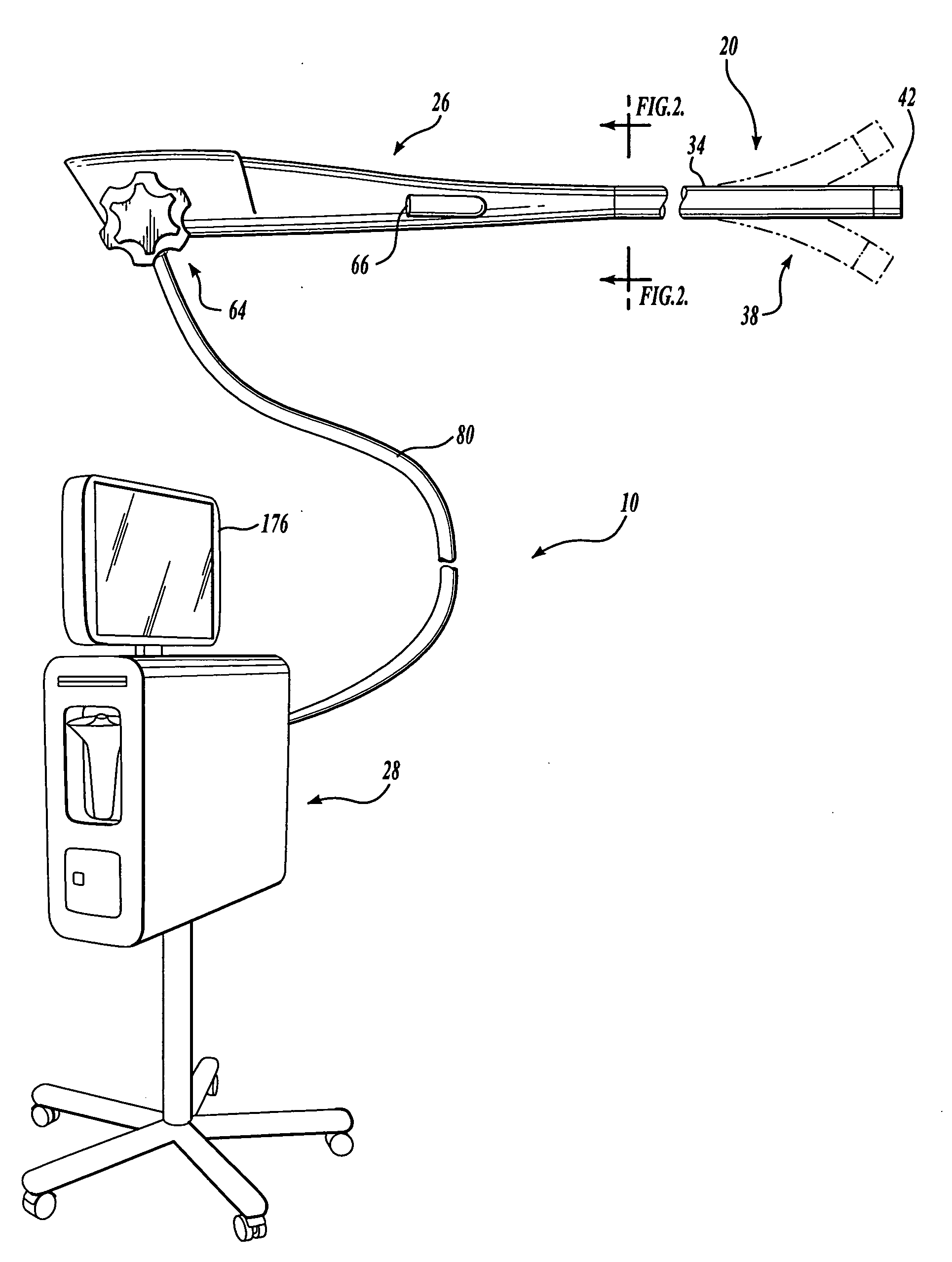
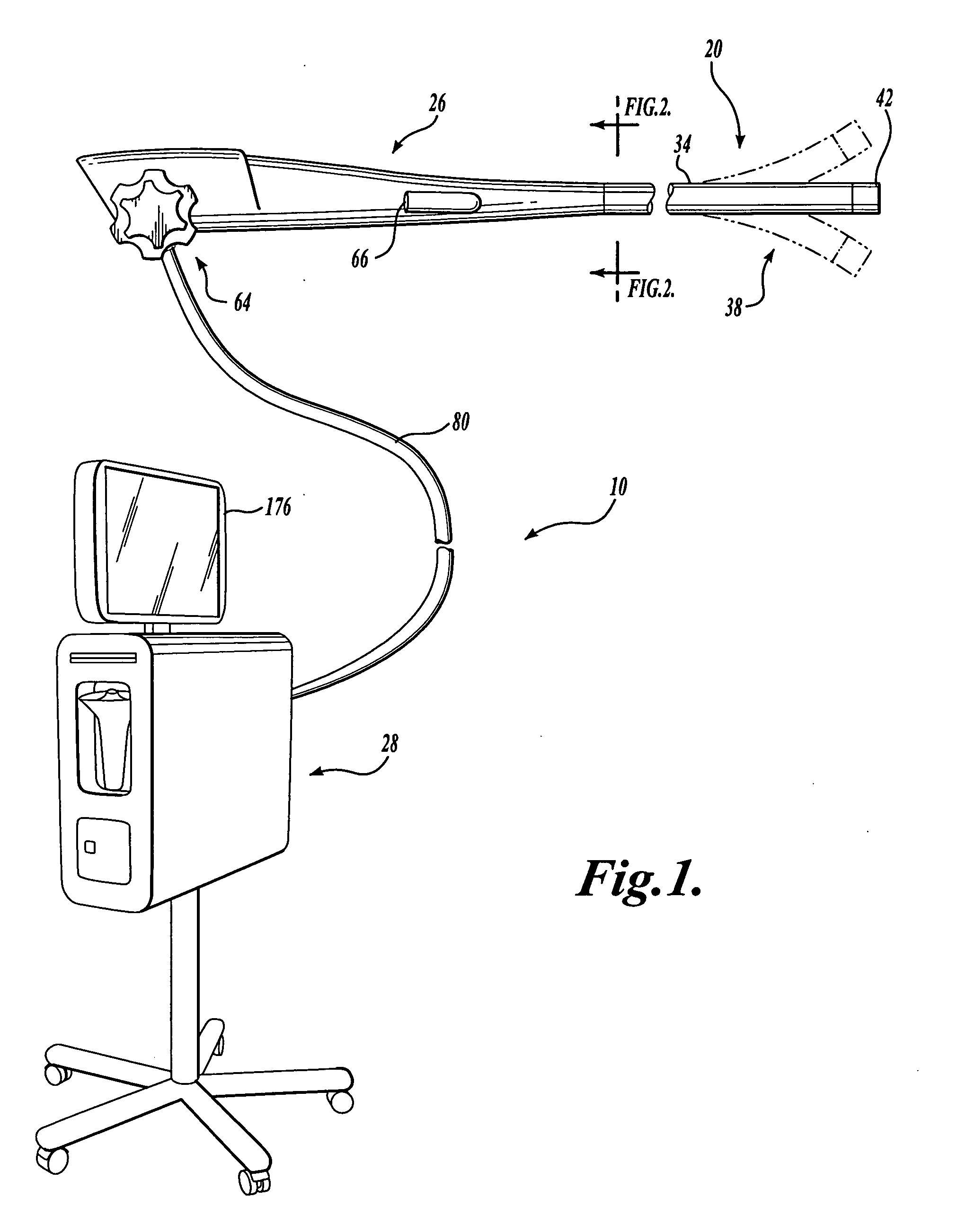
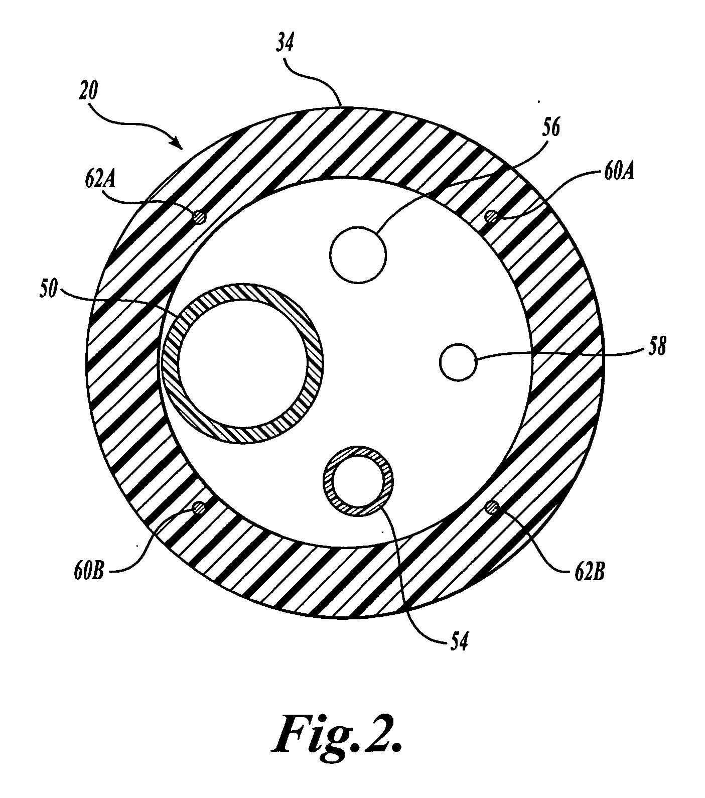
[0013] Embodiments of the present invention will now be described with reference to the accompanying drawings where like numerals correspond to like elements. Embodiments of the present invention are directed to systems of the type broadly applicable to numerous medical applications in which it is desirable to insert a steerable or non-steerable imaging device, catheter or similar device into a body lumen or passageway. The following description provides examples of medical systems that include an endoscopic probe, a capnographic device, and a control console for use in medical procedures.

[0014] Several embodiments of the present invention include medical devices that incorporate endoscopic features, such as illumination and visualization capabilities, for endoscopically viewing anatomical structures within the body. As such, embodiments of the present invention can be used for a variety of different diagnostic and interventional procedures, including upper endoscopy, endoscope ret...


PUM


Abstract

The system 10 includes an endoscopic probe 20 and an expired air sampling device 24 functionally connected to a control console 28. In use, the endoscopic probe 20 is routed through a body lumen of a patient to, for example, visualize a selected region of a patient's body. As the endoscopic probe 20 is routed through the body lumens, the expired air sampling device 24 collects expired air from the patient, generates signals indicative of patient respiratory status, and outputs the generated signals to the control console 28. The control console 28 processes the signals and monitors the respiratory status of the patient. If the respiratory status of the patient changes based on the processed signals of the expired air sampling device 24, the control console 28 may output an audible or visual alert signal.

Description

FIELD OF THE INVENTION [0001] The present invention relates to an endoscopic system, and in particular, to an endoscopic system having integrated patient respiratory status monitoring capabilities. BACKGROUND OF THE INVENTION [0002] Endoscopes have been used for many years in the medical field to look within a selected region of a patient's body, e.g., the colon or the upper gastrointestinal region. The endoscope is typically inserted through an orifice or a surgical incision into a body channel or cavity. Endoscopes are commonly used to perform surgical, therapeutic, diagnostic, or other medical procedures under direct visualization. Conventional endoscopes generally contain several endoscope components, such as fiber optic light guides, a fiber optic image guide, and a working channel. The endoscope can also be equipped with one or more instrument channels for surgical implements. These components are positioned within the lumen of an endoscope sheathing tube. Endoscopes may be ri...

Claims


Application Information

Patent Timeline
Patent Type & Authority Applications(United States)
IPC IPC(8): A61B1/00
CPCA61B1/00055A61B5/0836A61B1/267
Inventor COUVILLON, LUCIEN ALFRED JR.
Owner BOSTON SCI SCIMED INC
Why Eureka
Try Eureka