Ambulance cot with improved drop frame

Inactive Publication Date: 2007-07-26
FERNO WASHINGTON
View PDF9 Cites 23 Cited by
  • Summary
  • Abstract
  • Description
  • Claims
  • Application Information

AI Technical Summary

Benefits of technology

[0003] The present invention alleviates or at least ameliorates the above-mentioned difficulties by providing a simple arrangement that conveniently provides an improved drop frame having a wider range of motion to a cot construction. The cot construction of the present inve

Problems solved by technology

Although the prior art cots have been generally adequate for their intended purposes, they have not been satisfactory in all aspects.
For example, in

Method used


Image

  • Ambulance cot with improved drop frame
  • Ambulance cot with improved drop frame
  • Ambulance cot with improved drop frame

Examples


Embodiment Construction

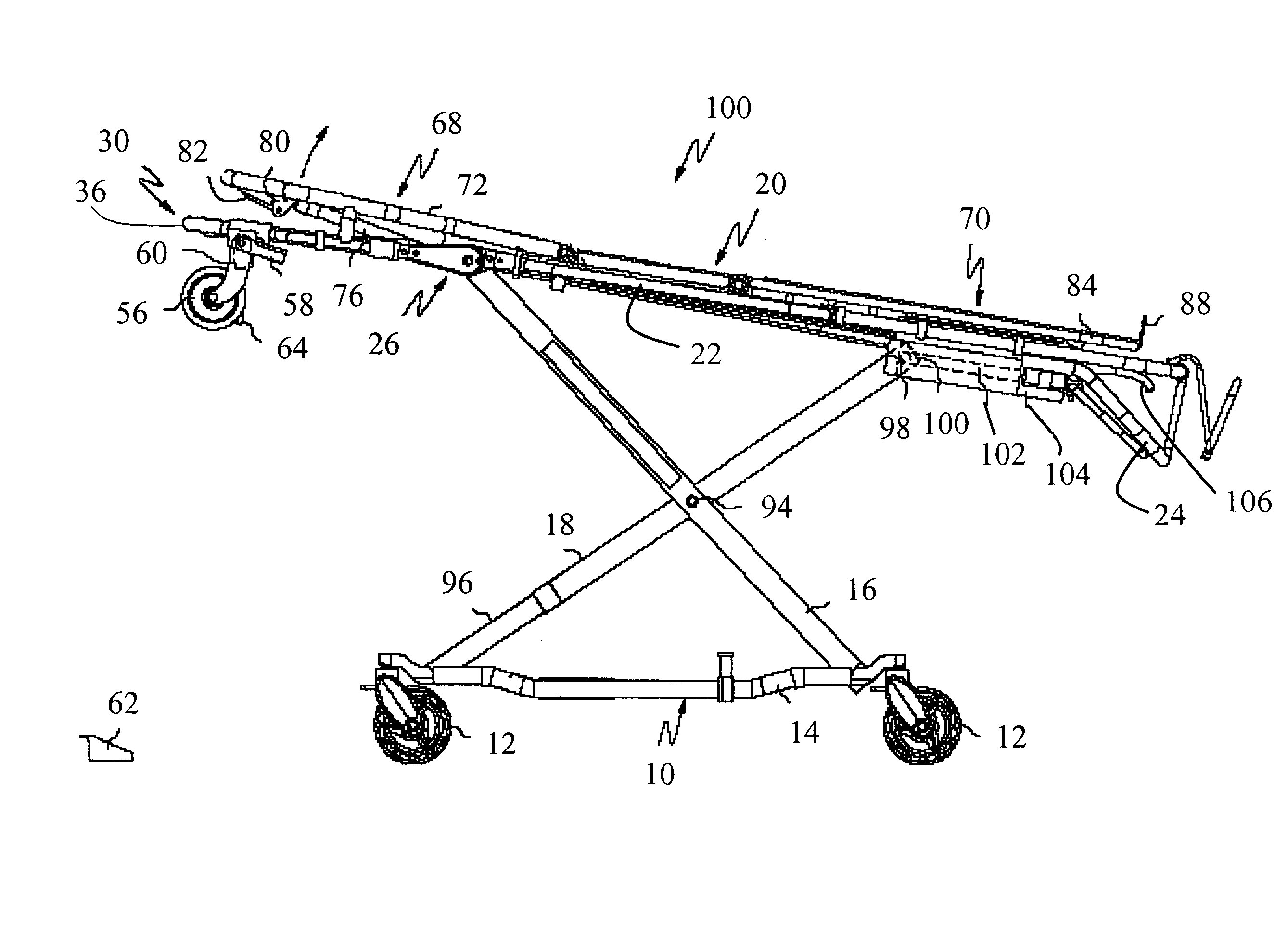
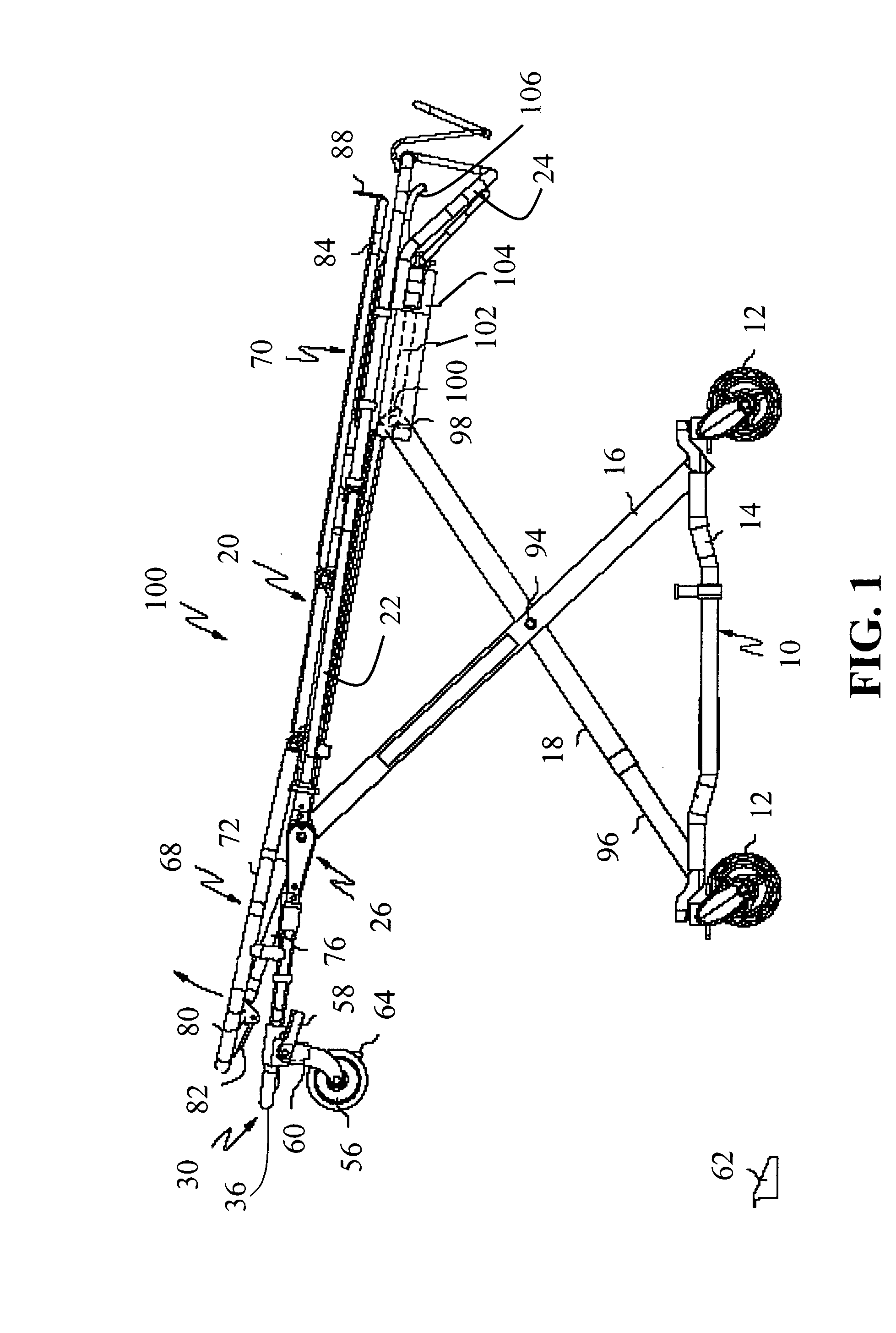
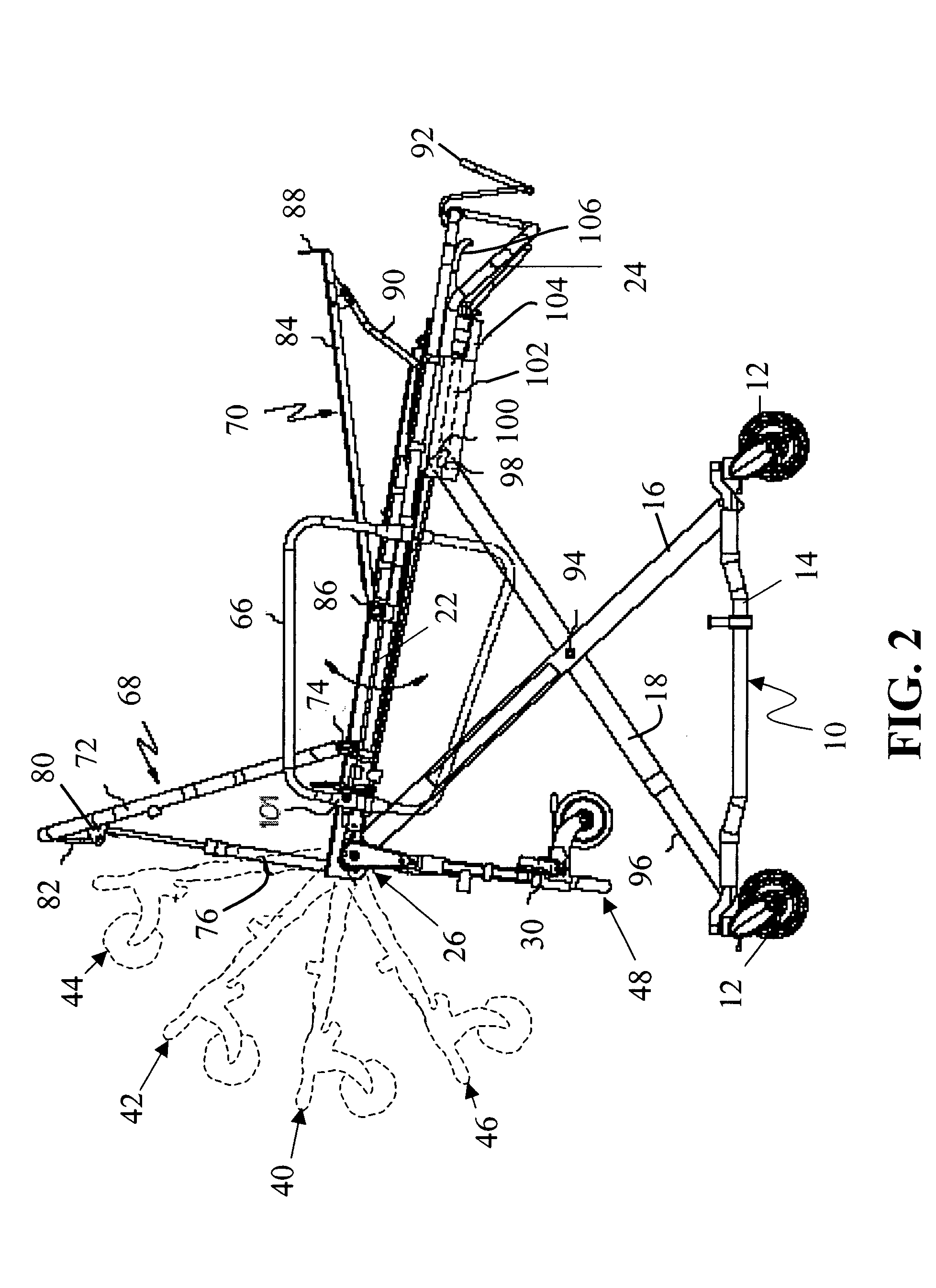
[0012] Referring first to FIGS. 1 and 2, illustrated is a cot structure embodiment of the invention indicated generally by symbol 100. The cot 100 has a rectangular undercarriage 10 mounting pairs of swivel caster wheels 12 at its opposite ends. It is to be appreciated that only one of the sides of the cot structure is illustrated for convenience, as the opposite side is substantially identical to the side shown. The undercarriage 10 includes opposing side frame members 14, which are interconnected by transverse frame members (not shown). Extending upwardly from the undercarriage 10 are pairs of cross forming frame members 16, 18, which serve to interconnect the undercarriage 10 with a cot frame 20.

[0013] Cot frame 20 includes opposing tubular side frame members 22 interconnected at the foot or trailing end by a transverse tubular end member 24. At their leading or forward ends, the side frame members 22 each terminate at a respective hinge pivot 26. Supported between the pair of h...


PUM


Abstract

A multiple level elevating cot adapted to be rolled into emergency vehicles, the cot having a wheeled undercarriage supporting a cot frame having a leading end and a trailing end, and adapted to selectively secure the cot frame in a plurality of elevational positions. The cot frame includes an improved drop frame having a wider range of motion to a cot construction. The cot frame is also provided with patient support features, such as positionable back, leg, and side arm supports.

Description

BACKGROUND OF THE INVENTION [0001] This invention relates to ambulance cots and more particularly with improvements to multi-level roll-in cots capable of being used in different types of emergency vehicles having cot-receiving floors. [0002] Ambulance cots typically comprise an essentially rectangular patient support frame with wheeled collapsible-leg assemblies enabling the stretcher to be stowed or loaded into the back of an ambulance. Examples of such prior art cots are disclosed in U.S. Pat. Nos. 4,097,941, 4,192,541, 4,767,148, 5,537,700, and 5,575,026. Although the prior art cots have been generally adequate for their intended purposes, they have not been satisfactory in all aspects. For example, in a confidence space with obstacles such as tables, chairs and / or desks, maneuvering a lowered cot can still possess some difficulties to an operator. SUMMARY OF THE INVENTION [0003] The present invention alleviates or at least ameliorates the above-mentioned difficulties by providi...

Claims


Application Information

Patent Timeline
IPC IPC(8): A61G7/015
CPCA61G1/0567A61G1/0212A61G1/0262A61G1/0237A61G1/02
Inventor WELLS, TIMOTHY
Owner FERNO WASHINGTON
Why Eureka
Try Eureka