
Optical horizontal measurement device

a horizontal measurement and optical technology, applied in the direction of active open surveying means, surveying instruments, instruments, etc., can solve the problems of high production cost and poor portability, difficult to draw a particular angle determined by a horizontal measurement device on a wall, and difficult to achieve the effect of a particular angl

Inactive Publication Date: 2007-07-26
LIN CHIN HUI
View PDF5 Cites 16 Cited by
  • Summary
  • Abstract
  • Description
  • Claims
  • Application Information

AI Technical Summary

Benefits of technology

[0016] Accordingly, the primary objective of the present invention is to provide an optical horizontal measurement device utilizes the character of light that it goes along a straight in a medium to have an optical module within the device, which is coupled with a knob so as to adjust the projection angle of a light beam freely and easily. Thereby, the light beam can be used to make engineering drawings.
[0018] It is a further objective of the present invention that the alignment and retention of the supplementary metallic plate on a wall is solved. The supplementary metallic plate is provided with an alignment hole that is aligned with a reference point on the wall when the plate is attached thereon. The horizontal position of the reference point is measured first. The optical horizontal measurement device is then mounted on the supplementary metallic plate, whereby a horizontal line needed can be quickly drawn. The supplementary metallic plate is further provided with a retaining hole to be pierced through with a nail for being mounted on a wall or to be attached on a wall by a double-sided adhesive pad. Correspondingly, the bottom of the lower shell is provided with a retaining portion with a capacity roughly the same as the size of the supplementary metallic plate for receiving the supplementary metallic plate. Therefore, the supplementary metallic plate can be stored in the optical horizontal measurement device, which enhances the portability.

Problems solved by technology

Some types of the horizontal measurement devices of the prior art comprise many optical components and motors and therefore have the problems of high production cost and poor portability.
Further, to use a horizontal measurement device on a vertical wall, the measurement location for the device should be fixed firstly, and then the other paths can be drawn, which is not easy at all.
Therefore, how to draw a line of particular angle determined by a horizontal measurement device on a wall is difficult.
As one other disadvantage, when a conventional optical horizontal measurement device is used to draw a horizontal line at a point.

Method used


Image

  • Optical horizontal measurement device
  • Optical horizontal measurement device
  • Optical horizontal measurement device

Examples


Embodiment Construction

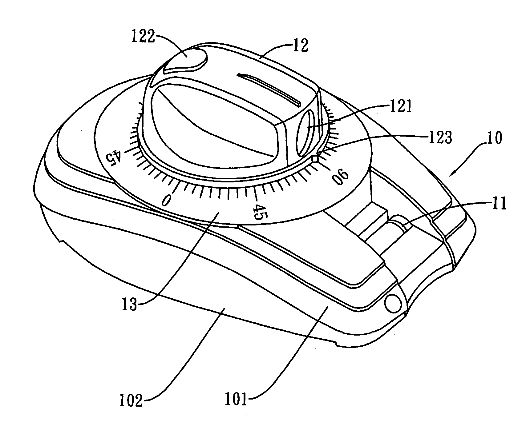
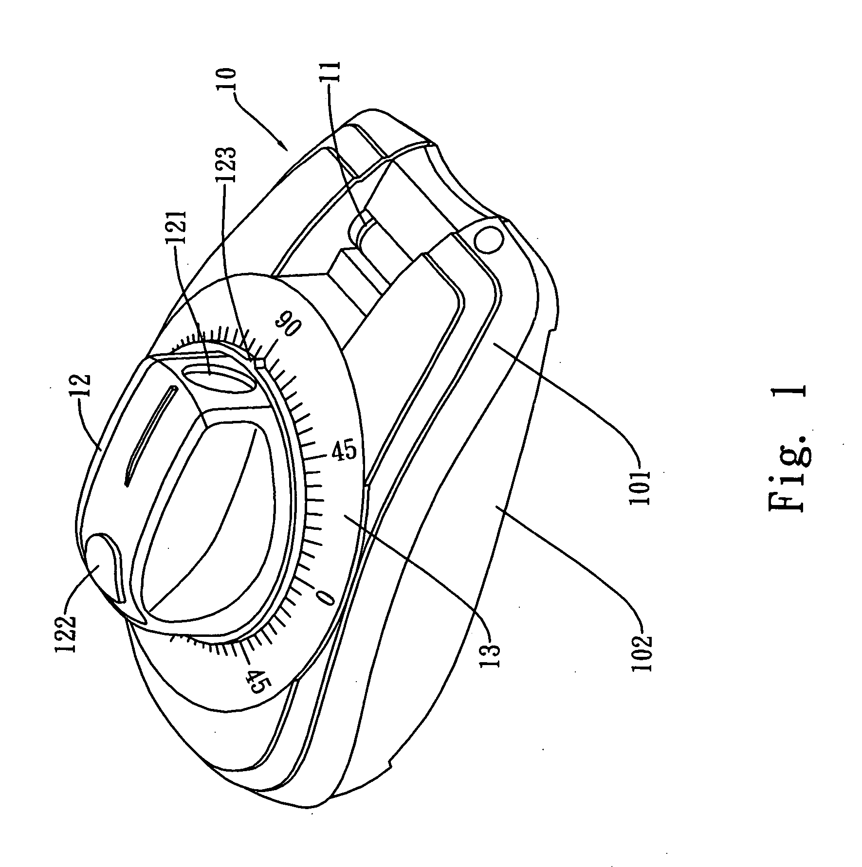
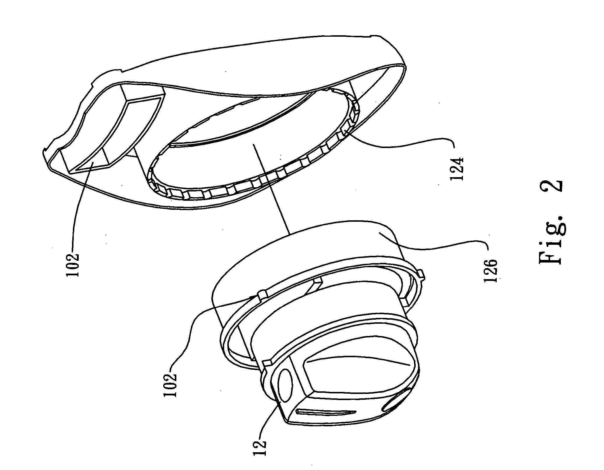
[0021] Referring to FIG. 1, an optical horizontal measurement device according to the present invention comprises a shell body 10, a bubble tube 11 and a knob 12; the knob 12 further contains a laser emitter (not shown in the figure). The shell body 10 further comprises an upper shell 101 and a lower shell 102. The bubble tube 11 is attached onto the inner wall of the shell body 10 and is exposed to the exterior through a window opened on the upper shell 101, whereby a person can observe the horizontal state of the optical horizontal measurement device. Further, the knob 12 is mounted on the upper shell 101 and has a front hole 121 for emitting a laser beam. A cursor 123 is formed underneath the hole 121, whereby the cursor 123 pointing against an indicator 13 surrounding the knob 12 will be used to determined an angle, as the laser beam is being fired. More specifically, what the cursor 123 indicates is the angle between the laser beam and the bubble tube 11. Further, there is a pu...


PUM


Abstract

An optical horizontal measurement device utilizes a knob containing a light-beam module for projecting a beam of light in a particular direction so as to perform an angular measurement, whereby we can draw a line in accordance with the beam. The optical horizontal measurement device is kept in a horizontal configuration based on a horizontal bubble tube. The optical horizontal measurement device further includes a supplementary metallic plate for being mounted firstly at a measurement location. The optical horizontal measurement device then can be locked with the supplementary metallic plate.

Description

FIELD OF THE INVENTION [0001] The present invention relates horizontal measurement devices, more particularly to an optical horizontal measurement device having a knob containing a light-beam module capable of sending a laser beam over a long distance, whereby the measurement of an angle between a reference direction and the direction the laser beam points can be done quickly. BACKGROUND OF THE INVENTION [0002] Some types of the horizontal measurement devices of the prior art comprise many optical components and motors and therefore have the problems of high production cost and poor portability. Further, the conventional optical horizontal measurement devices are for measuring horizontal or vertical lines. It is necessary that practical measurements for engineering uses require angle measurements for lines, which can be done by the conventional devices only through time-consuming iterative measurement. [0003] Further, to use a horizontal measurement device on a vertical wall, the me...

Claims


Application Information

Patent Timeline
IPC IPC(8): G01C15/00
CPCG01C15/14G01C15/004
Inventor LIN, CHIN-HUI
Owner LIN CHIN HUI
Learn More